Do you have a question about the Akai GX-65 and is the answer not in the manual?
| Brand | Akai |
|---|---|
| Model | GX-65 |
| Category | Stereo Receiver |
| Language | English |
Guidelines for safe servicing and post-service checks to ensure unit safety.
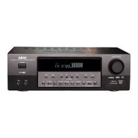
Explanation of the functions and operation of the front panel controls.
Step-by-step instructions for removing the main top cover of the unit.
Procedure for detaching the front panel assembly from the main chassis.
Guide to safely remove the entire mechanical block assembly.
General procedure for disassembling and assembling main mechanical parts.
Steps to replace the pinch roller block assembly.
Procedure for removing and installing the Record/Playback head.
Method to measure and verify the correct pressure of pinch rollers.
Procedure to check tape winding torque in play, FF, and REW modes.
Steps to adjust the tape playback speed using a frequency counter.
Instructions for adjusting tape guide height for optimal tape path.
Guide for aligning the record/playback head for proper azimuth.
Adjustment procedure for bias level when using Metal tape.
Adjustment procedure for bias level when using CrO2 tape.
Adjustment procedure for bias level when using Normal tape.
Adjustment of the bias oscillator frequency.
Adjustment to minimize resonance in the HX-Pro circuit.
Procedure for setting the recording input signal level.
Adjustment of the tape playback output signal level.
Tuning the playback equalizer for accurate frequency response.
Adjustment and function of the Multiplex filter.
Calibration of the recording level meter sensitivity.
List of critical spare parts recommended for stock for routine service.
Instructions on how to interpret and use the provided parts list.
Schematic and component layout for the Power Switch PC Board.
Overall connection diagram showing how different PCBs and components link.
Overview of the System Control PCB and other related circuit boards.
Detailed schematic for the System Control Printed Circuit Board.
Detailed schematic for the Pre Amplifier Printed Circuit Board.
Component layout and identification for the Pre Amplifier PC Board.