Do you have a question about the Akai GX-75 and is the answer not in the manual?
| Brand | Akai |
|---|---|
| Model | GX-75 |
| Category | Cassette Player |
| Language | English |
Essential safety guidelines to follow before and during repair work.
Procedures for confirming safety compliance after maintenance.
Instructions for adjusting the unit's voltage selector.
Explanation of symbols indicating the unit's target markets.
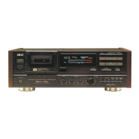
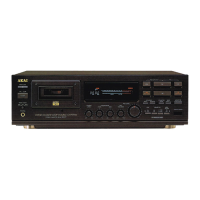
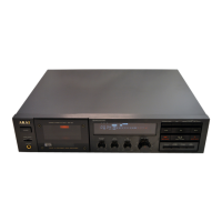
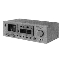
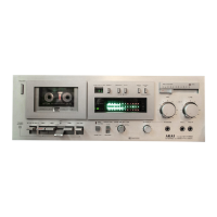
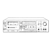
Buttons for power, cassette loading, play, stop, and tape winding.
Buttons for IPSS, memory, counter reset, display, and Dolby/MPX filters.
Controls for recording levels, bias, and level calibration.
Controls for headphone volume and timer start switch.
Steps to remove the unit's upper cover.
Procedure for detaching the front panel.
Instructions for removing the bottom cover.
Diagram showing component locations from the upper side.
Diagram showing component locations from the bottom side.
Detailed steps for removing the cassette lid case and decoration.
Procedure for removing the main mechanism block from the unit.
Steps to detach the motor block assembly.
Instructions for removing the cam motor and associated belt.
Procedure for replacing the Hall effect element.
Steps to remove the cam wheel and position potentiometer.
Guide for correctly reassembling the cam wheel and potentiometer.
Adjusting preset voltages for specific potentiometers.
Procedure for measuring pinch roller pressure.
Measuring winding torque in different playback modes.
Adjusting the physical projection of the Rec/Playback head.
Adjusting the vertical height of the tape guides.
Adjusting the vertical positioning of the Rec/Playback head.
Aligning the horizontal angle (azimuth) of the Rec/Playback head.
Guide on interpreting and using the parts list section.
Component list for the head base block assembly.
Component list for the main printed circuit board.
List of suggested spare parts for stocking and service.
Component list for the mecha (mechanism) block.
Component list for the motor block assembly.
Component list for various printed circuit board blocks.
Component list for the pre-amplifier printed circuit board.
Component list for the oscillator printed circuit board.
Component list for the headphone printed circuit board.
Component list for the system control printed circuit board.
Component list for the operation printed circuit board.
Component list for the timer printed circuit board.
Component list for the power supply printed circuit board.
Component list for the motor printed circuit board.
Component list for the final assembly block.
List of accessory items for the unit.
Details and parts for the RC-G95 remote control.
Schematic diagram of the motor printed circuit board.
Schematic diagram of the power supply printed circuit board.
Schematic diagram of the operation printed circuit board.
Diagram showing external and internal connections.
Schematic diagram for pre-amplifier and oscillator circuits.
Schematic diagram of the system control printed circuit board.
Layout diagrams showing component placement on various PCBs.