EasyManua.ls Logo

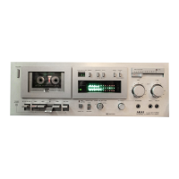
Akai gx-m50

Akai gx-m50
8 pages
To Next Page IconTo Next Page
To Previous Page IconTo Previous Page
Loading...
CONTROLS
CD
@
®
@
~
,
e"
J
.
..
-
' ,
1,1,1
'CT
I.:-,j
I:='.
r
@@@@@
@
(i)
POWER SWITCH
@ CASSETTE
RECEPT
ACLE
(with
tape
view
window)
Opens when
the
Eject Key
is
depressed.
@ PEAK!VU INDICATORS
When
the
peakjVU
button
is depressed,
the
peak
indicator
will li.ght.
If
not
depressed,
the
VU
indicator
will light.
CV
INDEX
COUNTER
AND RESET BUTTON
Tape indexing is made easy
with
this 3-digit
Index
Counter.
To
reset to
"000",
depress Reset
Button.
(§)
MEMORY
BUTTON
Set
Index
Counter
to
"000"
and depress
Memory
Button.
Automatic
Stop
at
this
setting
can
then
be
effected
from
Rewind.
*
If
the
rewind
(~)
and
play
(~
)
keys
are
depressed
simultaneously,
when
the
tape
counter
reaches
"000"
playback
will
start
auto;naticaJly.
® IPLS BUTTON
Depress this
button
for
instant
program
location.
See the IPLS
explanation
on
page
4.
,.
If
the
memory
button
is
depressed
at
the
~ame
time
as
the
IPLS
button
it will
lake
priority
and
the
rope
will
wInd
back
until
it
reaches
"000".
(j)
PEAKjVU
SELECTOR
BUTTON
Leave undepressed
for
VU and depress for peak.
® DOLBY
NR
SWITCH
Setting
the
Dolby
NR
Switch
to
ON
position
activates
the
Dolby
circuit
to
raise low level signals
[)
before
they
are recorded and lowers
them
by
precisely
the
same
amount
during
playback.
This
process eliminates
extraneous
and
superimposed
noise,
thus
also eliminating
tape
hiss.
When using
tape
recorded
with
the
Dolby
process,
it is
necessary
that
this
switch
be
set
10
ON
position
at
playback
also.
*
The
DolbY
NR
Indicator
near
the
FL
Bar
Meter
display
lights
when
the
Dolby
NR
Switch
is
depressed.
®
FL
DISPLAY
(FLO)
BAR
METERS
Show
the
recording levels
for
both
left
and right
channels.
Two
color
indication
differentiates
be-
tween
readout
above and below
"0"
dB.
@ REC MASTER
Enables Fade-in
and
Fade-out
recording
techniques
without
altering
the
optimum
recording level. When
not
in use
se
t to lO. See page 4.
@
RECORDING
INDICATOR
LAMP
Lights
when
the
Recording
Key
is
depressed.
@ LINE
RECORDING
LEVEL
CONTROLS
(left +
right)
Controls
line
recording
input
levels. Adjust while
observing
left
and
right
FL
Bar Meters. The inner
knob
controls
the
left
channel
and
the
outer
ring
controls
the
right channel.
They
can be
adjusted
separately
or
simultaneously.
@ MICROPHONE
RECORDING
LEVEL
CONTROLS
Controls
microphone
left-.)-right
recording
input
levels.
Adjust
while observing left and
right
FL
Bar
Meters. The inner
knob
controls
the
left
channel
and
the
outer
ring controls
the
right
channel.
They
can be adjusted separately
or
simultaneously.
@
LEFT
AND
RIGHT
MICROPHONE JACKS
For
stereo
recording,
connect
one
microphone
to
the
left
microphone
jack
and
one
to
the
right micro-
phone
jack.
For
monaural
recording,
connect
one
microphone
to
the
left
microphone
jack
MIC L
(MONO).
@ HEADPHONE JACK
\
Accommodates
stereo
headphones
of
8 ohms im-
pedance
for
monitoring
or
private
headphone
listen-
ing.
@
OUTPUT
LEVEL
CONTROL
Adjusts
output
volume
and
headphone
output
level.
@ BIAS
ADJUSTER
Changes the
amount
of
bias at
each
tape selector
switch
position
by a
maximum
of
±I0%. When
the
reference tape is used please
set
to the
chck
position
O.
@
TAPE
SELECTOR
This
control
should be
positioned
to
correspond
with
the
tape
being used.
That
is, for low-noise
tapes,
position
it
to
LN, for low-noise,
high-output
tapes
to
LH, for
chrome
tapes
to
Cr02
and
for
metal
tapes
to META L.
Refer
to
STANDARD
REFERENCE
AND
RECOM-
MENDED
TAPES.

Related product manuals