EasyManua.ls Logo

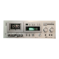
Akai gx-m50

Akai gx-m50
8 pages
To Next Page IconTo Next Page
To Previous Page IconTo Previous Page
Loading...
RECORDING
Connect
desired
program
source
to
appropriate
inputs
as
shown
in
CONNECTIONS
FOR
RECORDING.
1.
Connect
power
cord and
turn
on
Power
Switch.
2. Depress
Eject
key
and
load a
tape
(new
tapes
give
best results).
3.
Set
Index
Counter
to
"000".
4. Set
Monitor
Switch
to
SOURCE
position.
5.
Set
Tape
Selector
to
appropriate
tape
type.
Refer
to
STANDARD
REFERENCE
AND
RECOM-
MENDED
TAPES.
6.
For
Dolby
recording, depress
Dolby
NR Switch.
7. Adjust
and
balance recording
input
level
with
ap-
propriate
Recording
Level
Controls
while observing
the
FL
Bar Meters.
Refer
to
TAPE
MONITORING.
8. When an
optimum
recording level has been
deter-
mined,
while holding
the
Recording
(REC)
key
at
depressed
position,
depress
the
PLAY
(
~
)
key
to
begin recording.
To
monitor
recorded
signals,
set
Monitor
Switch
to
TAPE.
9.
Refer
to
the
section
on
REC
master
for professional
recording results.
10.
Automatic
Stop
will be
effected
at
the
end
of
the
tape.
To
stop
tape
during recording, depress
the
STOP
key.
Fox
Befter
Recordif\!l Results:
If
the
monitor switch is
set
to
SOURCE,
adjust-
ment
of
therecord.ir:lg level is
straightforward.
..
The
ltEC
master
should
be
~~t
at
maximu.tU, 1,0.
1.
Leave
the
peak/VU
button
undepressed
fOr
a
YU
readoul
Oil
the
bar
meter.
2,
:\djust
the
recording levels
so
that
the
readout
does
not
elCcee<lO
dB.
3. Depress,
the
peak/YU
meter
for
a peak read
out
on
the bar meter,
4. When
at
peak 0 dB
actually
means
+7
dB,
so
a~Just
the record.ing levels so
that
the
input
does
not
exceed
0
dB.
If
when
set
as
shove.
the
overall level is low
when
tape
monitoring,
you
may
adjust
thE'
level as
long as
there
is
no
distortion.
PLAYBACK
Make the necessary
connections
as
shown
in CON-
NECTIONS
FOR
PLAYBACK.
1.
Connect
power
cord
and
turn
on
Power
Switch.
2. Depress Eject
key
and load a
pre-recorded
tape.
3. Set
Monitor
Switch
to
TAPE
position.
4.
Set
Tape
Selector
to
appropriate
tape
selection.
Refer
to
STANDARD
REFERENCE
AND
RECOMMEND·
ED
TAPES.
5. Depress
PLAY
(
~
)
key
to
begin
playback.
6.
Adjust
Output
Level
Control
and
external
amplifier
controls.
7. Use
the
memory
and IPLS
buttons
to
repeat
a parti-
cular
programme
of
music. See
Controls
on
how
to
use
the
memory
and
the
section
on
IPLS.
«
Automatic
Stop
will
be
effected
at
the
end
of
the
tape.
To
stop
tape
travel
during
performance,
depress
STOP
key.
For
plaYback
of
Dolby
recorded
tapes,
depress
Dolby
NR
Switch.
(Leave
at
OFF
position
for
regular
playback.)
T
APE
MONITORING
The
three
head
system and
Tape
Monitor
Switch
facilitate
dual
monitoring.
For
precise recording level
adjustment,
set
Tape
Monitor
Switch
to
SOURCE
position
and
monitor
signals
through
headphones
(recommended
optional
accessory) while adjusting
Recording Level
Controls
before recording. Then set
the
machine
into
recording
mode.
By swit ching
the
Tape
Monitor
Switch
from SOURCE
to
TAPE
and
vice
versa,
recorded
signals can be
compared
with
the
source
signals. Confirm
that
the
program
is
positively
recorded
and
check
for
any
distortion
due
to overlevel
recordings.
Readjustment
of
Recording Level
Controls
may be necessary
due
to
variety
of
tape
qualities.
INST}!\NT
PROGRAM
LOCATING
SYSTEM
(IPLS)
The
instant
program
locating
system
detects
the
begin-
ning
of
the
programme
by
the
volume level and
the
time
constant
(the
length
of
silence).
For
this
reason,
the
intervals
between
each
musical
programme
must
be
at least
5 seconds for
the
system
to
work
effectively.
Please
keep
this
in
mind
especially
when
you
make
recordings
for
IPLS
playback.
For
the
same
reason,
classical
music
is
not
recommended
for IPLS
playback.
For
IPLS
Operation
simply depress
the
play
key
begin
playback,
and
depress
the
IPLS
button.
Depress rewind
(
----
)
or
fast forward (
~
)
buttons
and
the
play
(
~
)
button
simultaneously.
Once
the
desired place is
reached
playback
will
commence
automatically_
When
the
IPLS
button
is
not
depressed,
the
autoplay
me-
chanism
will
rewind
the
tape
back
to
the
beginning
where-
upon
playback
wiJJ
commence
automatically
if
the
play
key (
~)
is
depressed
at
t.he
same
time.
REC
MASTER
Is a
very
convenient
feature
which enables
the
record-
ing level
to
be
altered
independently
from
the
opti-
mum
recording level
marked
with
either
the
LINE
or
MIC
recording
level controls.
The
optimum
recording
level
takes
priority
when
the
REC Master is set
to
its
maximum
position
of
10.
Try
fade-in at
the
beginning
of
a
programme
by
sliding
the
REC Master
from
where
there
will be
no
volume to 10,
the
optimum
recording
level. Similarly,
fade-out,
the
gradual decrease
of
volume
at
the
end
of
a
'programme,
can be
effected
by
sliding
the
REC Master
to
O.
EmploY it also
when
mixing
LINE
and
MIC recordings
for
the
professional
touch.
The
R£C
master
cannot
be used
for
independent
left
and
right
channel
alteration.
BIAS
ADJUSTMENT
This
deck
is supplied
with
a bias
adjuster
which can
vary slightly
the
amount
of
bias according
to
each
tape
selector position.
For
normal
recording
there
should
be
no
problems
if
the
bias
adjuster
is
set
to
O.
If
bias
adjustment
is
required:
I.
At
the
recording
level
position,
-20dB,
record
the
inter-station
noise
compare
the
source and
recorded
tone
quality
by
switching
the
monitor
switch be-
tween
TAPE
and
SOURCE.
2. When
the
monitor
switch is set to
TAPE,
if
the
sound
is harsh
tum
the bias
adjuster
clockwise
to
the +side
and
if
soft,
counterclockwise
to
the
- side.
3.
Repeat
step
1 and
adjust
until
the
sound
is
the
same
for
TAPE and
SO
URCE positions.
Even
if
the
brand
is
the
same,
(here
are
differences
between
C·60
and
C-90
tapes
due
1.0
the
thickness.
The
Dias
adjuster
does
uot
work
during
playback.
MIXING
The
input
through
the
LINE
input
and
the
MIC
input
can
be
mixed
and
recorded.
1.
Connect
the
microphones.
2.
Connect
FM
tuner
or
another
deck
to
the
LINE
input
jacks.
If
a
turntable
is
connected,
connect
via a preamplifier section.
3.
Adjust
the
level
of
the
microphone
input
with
the
MIC recording level
control
and
the
input
from
the
component
connected
to
the
LINE
IN
jacks
with
the
LINE
recording level.
ill

Related product manuals