Defrost finished by time alarm
The icon I is displayed when a defrost ends for maximum time. (The Signal end defrost time must be configured as
“Yes”).
The sound alarm and alarm relay is not activated.
Low pressure alarm
It displays the LOW PRESSURE ALARM message when low pressure is detected in the circuit, or if pressure does not
increase during the starting operation from pump down (See page 21). In both cases, there should be a low pressure
controller connected to the unit (See page 12).
The compressor stops and activates the sound alarm and alarm relay is not activated.
Compressor safety chain alarm
It displays the COMP. SAFETY ALARM message, if any component in the compressor's safety chain triggers
(compressor motor guard, thermistors or high pressure controller).
The compressor stops and activates the sound alarm and alarm relay.
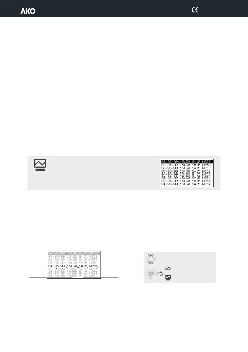
9.7.- Data logging
The probe designed for temperature logging depends on the probe configuration (See page 14).
Press the P and O keys at the same time for 5 seconds to access data logging.
Data is saved in log blocks and the unit can store up to 366 blocks and each block contains 96 logs.
Each log contains the temperature measured by the unit, and the data and time of this measurement.
The "registry interval” parameter defines the time that passes between the capture of a datum and the next one.
When the last available block (N365) has been completed, the unit starts again with the first block (N000), therefore,
the time interval the unit is capable of storing depends on the configured log interval.
Use the N or Q keys to select a block and press SET to display the logged data.
Display of the logged data.
Defrost finished by time alarm
The icon I is displayed when a defrost ends for maximum time. (The Signal end defrost time must be configured as
“Yes”).
The sound alarm and alarm relay is not activated.
Low pressure alarm
It displays the LOW PRESSURE ALARM message when low pressure is detected in the circuit, or if pressure does not
increase during the starting operation from pump down (See page 21). In both cases, there should be a low pressure
controller connected to the unit (See page 12).
The compressor stops and activates the sound alarm and alarm relay is not activated.
Compressor safety chain alarm
It displays the COMP. SAFETY ALARM message, if any component in the compressor's safety chain triggers
(compressor motor guard, thermistors or high pressure controller).
The compressor stops and activates the sound alarm and alarm relay.
9.7.- Data logging
The probe designed for temperature logging depends on the probe configuration (See page 14).
Press the P and O keys at the same time for 5 seconds to access data logging.
Data is saved in log blocks and the unit can store up to 366 blocks and each block contains 96 logs.
Each log contains the temperature measured by the unit, and the data and time of this measurement.
The "registry interval” parameter defines the time that passes between the capture of a datum and the next one.
When the last available block (N365) has been completed, the unit starts again with the first block (N000), therefore,
the time interval the unit is capable of storing depends on the configured log interval.
Use the N or Q keys to select a block and press SET to display the logged data.
Log date
Block in
use
Log time
Log
interval
Block no.
SET
Scrolling through logs
Data display
Graph display
SET
23
1565H041 Ed.03