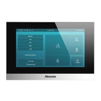
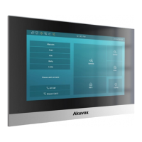
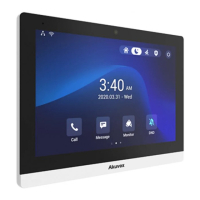
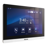
The Akuvox S563 is a smart intercom device designed for secure and convenient access control. It features a sleek design with a touch screen interface, speaker, and microphone, making it suitable for various residential and commercial applications.
Function Description:
The S563 serves as a central point for communication and access management. It allows users to make audio and video calls, monitor entry points, and unlock doors remotely. The device integrates with network video recorders (NVRs) and SIP video phones, enabling a comprehensive security and communication system. Its touch screen displays the current time, date, and weather, along with quick access icons for "Call," "Message," "Monitor," and "DND" (Do Not Disturb) functions.
Important Technical Specifications:
Voltage and Current Specifications:
- Power Source: PoE (Power over Ethernet) or 12VDC 1A power adapter.
AWG Sizes and Properties Table (for 12VDC 1A power supply):
- AWG 16:
- Resistance (ohm/km): 13.5
- Cross-sectional Area (mm²): 1.318
- Wire Length (m): ≤50
- AWG 18:
- Resistance (ohm/km): 21.4
- Cross-sectional Area (mm²): 0.8107
- Wire Length (m): ≤50
- AWG 20:
- Resistance (ohm/km): 33.9
- Cross-sectional Area (mm²): 0.5189
- Wire Length (m): ≤50
- AWG 22:
- Resistance (ohm/km): 48.5
- Cross-sectional Area (mm²): 0.3247
- Wire Length (m): ≤40
- AWG 24:
- Resistance (ohm/km): 79.6
- Cross-sectional Area (mm²): 0.2047
- Wire Length (m): ≤20
Wiring Interface:
The device provides various connection points for power, doorbell, RS485, security relay, and door lock.
- Power Adapter: PWR_IN, PWR_GND-
- Doorbell Button: BELL (Doorbell Input)
- RS485: RS485_B, RS485_A
- Security Relay (RELAY OUTPUT): NC (Normally Closed), COM (Common), NO (Normally Open)
- Diode: For door lock (SDC 30V)
- LAN Ports: PC(PON), LAN(POE)
- Alarm Input: GND, I08, I07, I06, I05, I04, I03, I02, I01
Usage Features:
Unpacking and Installation:
The S563 comes with essential accessories for installation, including:
- S563 device (1x)
- Allen wrench (2x)
- Wall-mounting bracket (USA) (1x)
- Wall-mounting bracket (EU) (1x)
- M2x5 hex socket screw (2x)
- M4x20 crosshead screw (2x)
- 8-Pin cable (1x)
- 10-Pin cable (1x)
- Foam (2x)
- #6-30 Phillips machine screw (2x)
- ST3x20 crosshead screw (2x)
- Plastic wall anchors (2x)
- ST4x20 crosshead screw (2x)
- Diode (1x)
Installation can be performed with various junction box types (86, 118, round) or directly on the wall without an electrical junction box.
- Bracket Installation: Secure the appropriate wall-mounting bracket (EU or USA) to the junction box or directly to the wall using the provided screws and plastic wall anchors. For direct wall mounting, a square hole (52x48x12mm) needs to be cut, and two 6mm holes (20mm deep, 60mm apart) drilled for anchors. Foams should be applied to the top and bottom of the bracket for direct wall mounting.
- Device Mounting: Plug cables from the wall into the corresponding interfaces on the device's back cover. Tilt the device 15° to align slots with bracket hooks, then press down to secure it against the wall. Finally, use the Allen wrench to secure two M2x5 hex socket screws at the bottom of the device.
Device Removal:
To remove the device, use the Allen wrench to remove the two M2x5 crosshead screws at the bottom. Tilt the device 15° and push it up to detach it from the bracket.
Application Network Topology:
The S563 supports a LAN-based network topology, allowing connection to SIP video phones, network video recorders (NVRs), and PCs (third-party). It utilizes PoE for power and data transmission, connecting to other door phones (S563) and network devices.
Device Test:
After installation, verify the device status:
- Network: Navigate to "Setting > System Info" to check the IP address and network status. A proper IP address indicates a working network.
- Intercom: Dial a callee's or APT number and press the "Dial" icon for an audio call or the "Video" icon for a video call. Successful calls confirm correct configuration.
- Access Control: Press the "Unlock" icon on the monitor interface to unlock the door.
Maintenance Features:
Requirements for Placement and Usage:
- Place the device away from direct sunlight and strong light sources to prevent damage.
- Avoid high-temperature, humid environments, or areas with magnetic fields.
- Install the device securely on a flat surface to prevent falling and potential injuries/property loss.
- Do not place the device near heating objects.
- Maintain a distance of at least 2 meters from light sources and 3 meters from windows and doors.
Cautions:
- Avoid knocking the device with hard objects.
- Do not press hard on the device screen.
- Do not expose the device to chemical products (alcohol, acid, disinfectants).
- Ensure accurate screw hole diameters and depths during installation to prevent loosening. Use glue if screw holes are too large.
- Clean the device surface gently with a wet cloth, then wipe dry.
- If abnormal situations (uncommon sound, smell) occur, power off the device immediately and contact Akuvox Technical Team.
Warning! (Safety Precautions):
- To ensure safety, avoid touching the power core, power adapter, and device with wet hands.
- Do not bend or pull the power core, or damage any components.
- Only use qualified power adapters and power cords.
- Be careful not to stand directly under the device during installation or maintenance to avoid personal injuries from it falling.
Warranty:
- Akuvox warranty does not cover intentional mechanical damage or destruction due to improper installation.
- Do not attempt to modify, alter, maintain, or repair the device yourself.
- The warranty does not apply to damages caused by unauthorized personnel. Contact Akuvox Technical Team for repairs.
Over-voltage Protection:
It is recommended to wire a diode into the door lock circuit to protect against over-voltage. Connect the diode's anode to the negative cable of the lock and the cathode to the positive cable of the lock.