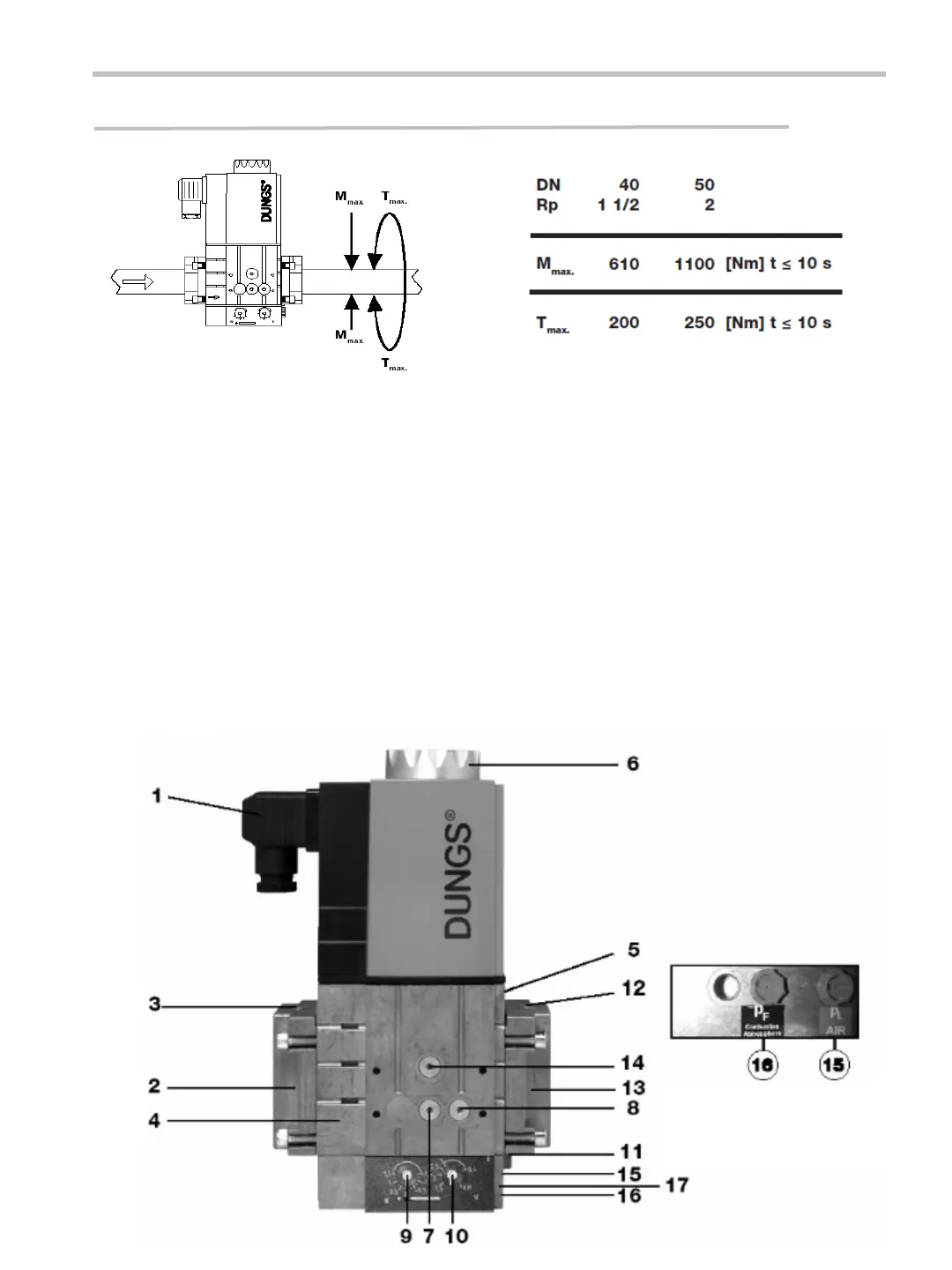
GAS MULTIBLOCK MBC 700VEF MBC 1200 VEF SETTINGS
39
The device should not be used as a lever.
ASSEMBLY
1. Electrical connection for valves.
2. Input flange
3. Pressure connection G 1/8 upstream of filter.
4. Filter
5. Type plate
6. Cover
7. p
e
Test point connection G1/8 upstream of V1, possible on both sides.
8. p
a
Test point connecion G1/8 downstream of V2, possible on both sides.
9. Setting screw. Zero point adjustment N.
10. Setting screw. Ratio V.
11. Vent nozzle G 1/8.
12. Pressure connection G 1/8. Burner pressure PBr
13. Output flange.
14. P Test point connection G 1/8. Upstream of V1. Possible on two sides.
15. Pressure connection G1/8. Blower pressure PL.
16. Pressure connection G1/8. Combustion chamber pressure PF.
17. Optional: Pulse line PBr


 To Next Page