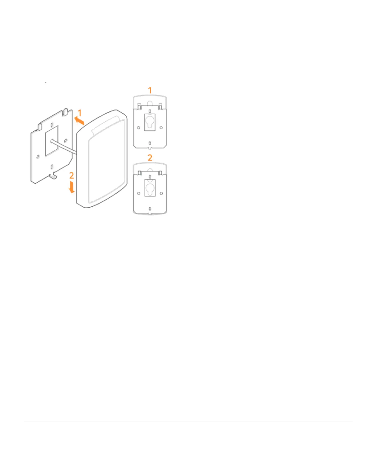
Secure the reader to the wall plate
• Align the reader so that the tabs of the base plate slide into the slots on the wall plate.
• Slide the reader into position.
• Secure the reader to the mounting plate using the supplied #4-40 screw or pin-in-Torx.
Power and test the reader
Power the reader and wait for the power-up LED beep sequence to complete. Present a valid credential to the reader
and the light-bar will turn green. If the test fails, check the wiring.
Additional information
Installation tips
• When connecting the reader to a Wiegand panel, connect the Green wire to Data 0 and the White wire to Data 1.
• When connecting the reader to an OSDP panel, connect the Green wire to RS485A and the White wire to RS485B.
• For an OSDP system, verify that the panel is successfully communicating with the reader prior to reading a
badge or pressing a key.
Set the reader for Wiegand or OSDP
Note: Alarm.com readers are expected to ship in Weigand/Auto-Detect mode. Once a reader has been configured for
OSDP using the Auto-Detect process, it will remain in OSDP until the reader is put back into Weigand/Auto-Detect
mode.
The process for setting a reader for Wiegand or OSDP varies depending on the firmware version.
https://answers.alarm.com/Partner/Installation_and_Troubleshooting/Access_Control/Access_Control_Entry%2F%2FExit_De…
Updated: Mon, 08 Apr 2024 20:56:52 GMT
4
 Loading...