1
GENERAL DESCRIPTION
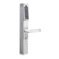
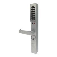
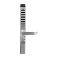
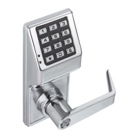
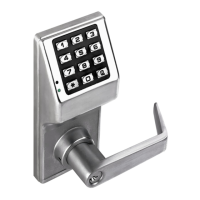
The DL1200ET, DL1300ET and PDL1300ET are
manually programmable narrow stile entry trim for nar-
row stile aluminum doors. The following specialized
templates are designed to utilize existing panic exit de-
vice mounting holes:
• Arrow
™
S1200/S1250 series (WI1758)
• Corbin Russwin
®
ED8200/ED8400 series (WI1759)
• DCI 1200/1300 series (WI1760)
• Dorma 5300 series (WI1761)
• Dor-O-Matic
®
2090 series (WI1762)
• Jackson
®
1095 series (WI1763)
• Von Duprin
®
22 series (WI1764)
• Von Duprin
®
33/35 series (WI1765)
All mounting hole locations shown on the above instal-
lation templates are referenced from the existing
mounting holes of the previously installed panic exit
device hardware.
When a valid User Code is entered, the DL1200ET,
DL1300ET or PDL1300ET retracts a tailpiece, allowing
the tailpiece to unlock the device when the lever is
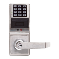
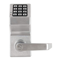
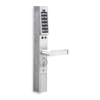
pressed down. PDL (proximity) models allow either a
User Code or the presentation of a proximity card to
unlock the device.
A User Code can be programmed to enable Passage
Mode to allow unrestricted passage until another ac-
cess code is entered, re-locking the trim. All locks are
equipped with a mechanical metal key override. See
WI1686, WI1687 or WI1688 to enable Passage Mode
and other programming features.
MECHANICAL FEATURES
The overall enclosure housing is 14 3/8" inches high, 1
5/8" inches deep and 1¾" inches wide. The trim is
through-bolted to the stile of the door (using four #10
screws) and is secured on the interior side of the door.
Supported stile thickness is 1¾".
• The DL1200ET series supports 100 User Codes,
fingertip keypad programmable.
• The DL1300ET series supports 2000 User Codes
and includes a 40,000 event audit trail and a 500
event schedule. Keypad or PC programmable.
• The PDL1300ET series supports 2000 User Code
or proximity card users and includes a 40,000 event
audit trail and a 500 event schedule. Keypad or PC
programmable.
• Aluminum door retrofit outside trim for Arrow
™
S1200/S1250 series, DCI 1200/1300 series, Corbin
Russwin
®
ED8200/ED8400 series, 33/35 and 22
series, Dor-O-Matic
®
2090 series, Jackson
®
1095
DL1200ET - DL1300ET - PDL1300ET
NARROW STILE ACCESS LOCKS
MOUNTING AND INSTALLATION
INSTRUCTIONS
WI1684A 10/11
345 Bayview Avenue
Amityville, New York 11701
For Sales and Repairs 1-800-ALA-LOCK
For Technical Service 1-800-645-9440
Publicly traded on NASDAQ Symbol: NSSC
© ALARM LOCK 2011
series and Dorma 5300 series locks.
• Familiar Trilogy
®
programming & electronics.
• All-metal, vandal-resistant 12-button keypad sup-
ports 3-6 digit PIN codes (3-5 digits on the
DL1200ET), and multilevel user hierarchy (master,
manager, supervisor and basic users).
• Keypad or PC programmable (see model informa-
tion). Quickly and easily add or delete users and
enter "passage mode", service codes, group lock-
out & group enable.
• HID proximity Prox ID cards, keyfobs and tags sup-
ported in PDL1300 series which features a built-in
proximity reader (high security applications can re-
quire the use of both User PIN Code plus proximity
ID card for access).
• Real time clock and PC programmable automatic
lock / unlock scheduling for 500 events (1300 Series
models).
• Wide weatherproof operating range from -31ºF to
151ºF (-35ºC to 66ºC).
• Provides 100,000 operations using off-the-shelf long
life DL123A lithium batteries, and includes audible
and visual low battery alert.
• Non-handed; fully field-reversible.
• Mechanical key override; interchangeable cores
supported (Corbin/Russwin, Yale, Schlage,
Medeco).
• Mortise Cylinder, 1¼" supplied (supports 1-1/8",
1¼", 1-3/8" and 1½".
• Stile thickness 1¾".
TABLE OF CONTENTS
GENERAL DESCRIPTION ............................................................. 1
MECHANICAL FEATURES ............................................................ 1
MECHANICAL OVERRIDE CYLINDER CAMS .......................2
CYLINDER COLLARS ............................................................ 2
MOUNTING AND INSTALLATION ................................................. 3
INSTALL CYLINDER ................................................................ 3
INSTALL THE LEVER ............................................................... 4
PREPARE THE DOOR FOR "THROUGH-BOLTING" ........ 3
INSTALL TAILPIECE ON LOCK ........................................ 4
CONNECT BATTERIES .................................................... 4
INSTALL LOCK ON DOOR ................................................ 5
PROGRAMMING THE LOCK ......................................................... 5
TEST DL LOCK OPERATION
AFTER INSTALLATION ................................................................ 6
NAPCO LIMITED WARRANTY ...................................................... 8