7
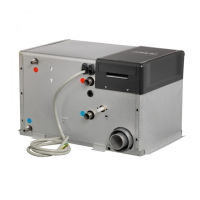
3:4 REPLACING SPARK ELECTRODE
When replacing the spark electrode, also replace the
amesensor.
1. Detach the burner as per instructions in 3:3.
2. Release the screws (g. 6A) and remove the spark
electrode (g. 6B).
3. Fit the new electrode, and secure it. Check that the distance
between the points on the spark electrode is 2.5-3.5mm,
and that this is correctly positioned.
4. Ret the burner according to 3.3, and test-start the boiler.
3:5 REPLACING THE FLAME SENSOR
Whenreplacingtheamesensoralsoreplacethespark
electrode.
1. Detach the burner in accordance with 3:3.
2. Release the screws (g. 6 C) and remove the
ame sensor (g. 6 D).
3. Fit the new ame sensor, ensuring that the tip of the ame
sensor is positioned above the burner in accordance with
g. 6., and secure.
4. Fit the burner in accordance with 3:3 and test-start
the boiler.
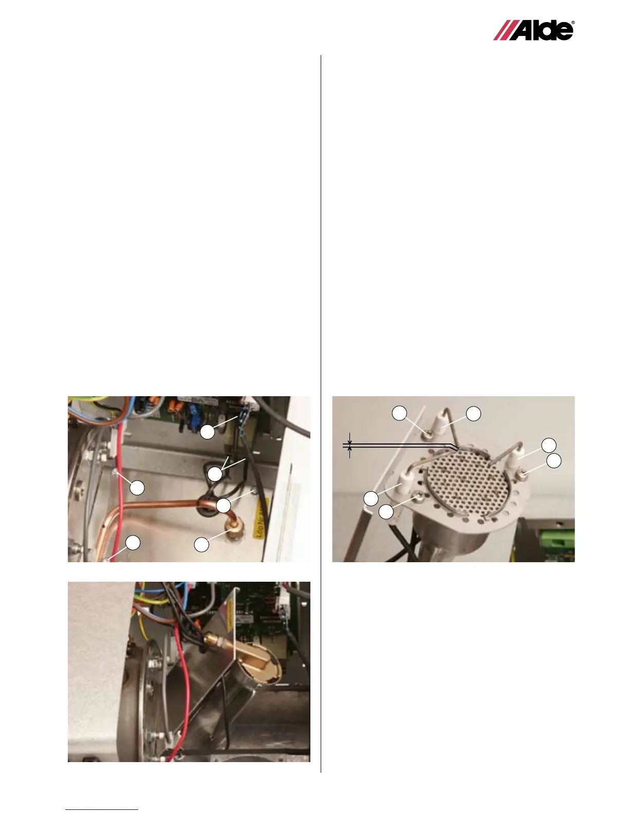
3:3 REPLACING A BURNER
1. Remove the service panel on the boiler.
2. Release the fan in accordance with 3:2.
3. Remove the sensor cable (g. 4A) and spark electrode
cables (g. 4B) from the printed circuit board.
4. Using two spanners, unscrew the gas pipe from the burner
(g. 4C) and the solenoid valve (g. 7B).
5. Remove the three screws (g. 4D) on the end plate of the
burner against the burner housing.
6. Pull the end plate with burner straight out of the burner
housing (see g. 5).
7. Fit the new burner following the instructions in the reverse
order.
8. Using two spanners, tighten the nuts on the solenoid valve
and on the burner to 7-9 Nm.
Remember to check that the cones are correctly tted to
the pipe.
NB! Check the system and connections for leaks with leak
detector spray when the boiler is running.
9. Connect ame sensor cables and spark electrode cables to
the printed circuit board.
10. Ret the service panel and test run the boiler.
Fig 4.
Fig 5.
A
B
C
D
D
D
Fig 6.
B
A
A
D
B
2,5-3,5 mm
C