23
EN
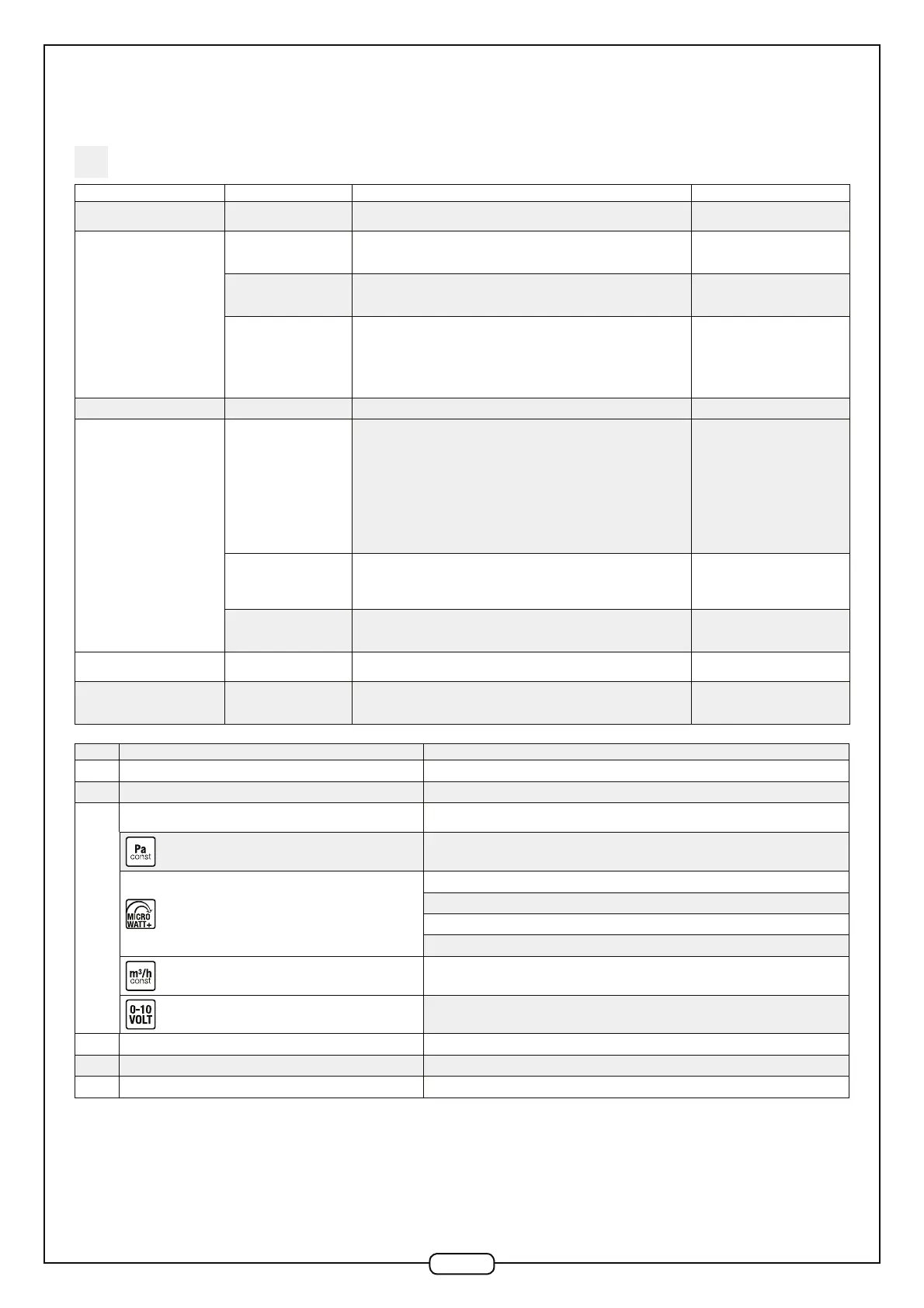
Symptom 1 Symptom 2 Verifications Action
A fault is displayed on the remote
control
- See error code table below
The fan unit will not start
The remote control screen
(depending on version) is
switched on
- Check all wiring
- Check the motor: must be supplied directly with 230V~. Activate the motor run
control
Replace the faulty part: Control PCB
or motor
The remote control screen
(depending on version) is
switched off
- Check all wiring.
- Check fuse on Control PCB
Replace the fault part: remote
control or Control PCB.
Version without remote
control
- Check all wiring
- Check capacitor (depending on version)
- Check speed controller fuse
- Check voltage at the output of the speed controller (depending on version)
- Check the motor: 230V AC direct supply. In addition, for EC motors (EasyVEC
®
Compact 2000): activate the motor run control
Replace the faulty part: fuse,
capacitor, speed controller or motor
The fan unit starts and then stops - Check all wiring.
The fan does not run at the
selected set-point
Low speed
"Check that the impeller is not rubbing against the casing
- Check the capacitor (depending on version).
- Adjust the speed controller (depending on version).
- Check the output voltage from the speed controller or Control PCB (depending
on version).
- Check the functioning of the pressure sensor(s) (depending on version,
simulating a slight over or under pressure in the pressure tubes.
- Check the motor: Directly from 230V AC supply In addition, for EC motors
(EasyVEC
®
Compact 2000 & micro-watt/micro-watt + versions): activate the
motor run control (contact Technical Support)"
Replace the faulty part: capacitor,
additional pressure sensor (micro-
watt + version), speed controller,
electronic control PCB or motor
High speed
- Check the fire mode thermo-trip device and wiring (depending on version)
- Check the condition, position and connectivity of pressure tubes (depending on
version), unblock if necessary.
- Check the above points (low speed).
Replace the faulty part: thermo-trip
device (triggering fire mode). See
above (low speed)
The speed does not change
when the set point is
changed
- Inspect the aeraulic network looking for leaks.
- Check the above points (high speed - low speed)
- See A45 above (high speed - low
speed)
The fan rotates in the wrong
direction
- Check the wiring in the motor terminal unit (EasyVEC® 1000 to 2500)
The micro-watt+ and constant
flow rate modes are no longer
available (micro-watt+ version)
- Check the wiring on the additional pressure sensor (micro-watt+ version)
Change the additional pressure
sensor (micro-watt+ version)
N° Meaning Diagnostics/Solutions
E.50 Motor speed return = 0 rpm Motor disconnected or fan stuck or motor U/S
E.51 Motor speed return < 100 rpm Fan is rubbing or motor is U/S
E.52
Fan does not reach minimum pressure set point
Check full system (network load and loss through leakage)
Check the state and connectivity of capillaries, unblock if necessary.
Constant pressure: 80 Pa.
Self-balanced regulated pressure: 50 Pa
Humidity-controlled regulated pressure: 80 Pa
T-Flow regulated pressure: 110 Pa
Expert regulated pressure: 50 Pa
Constant airflow: NA
Control 0-10 V: NA
E.53 Incoherent pressure reading (too high) Pressure sensor U/S
E.88 Communications fault involving remote control Remote control U/S
E.251 Operating in Fire Mode, thermo-contact circuit open Thermocontact circuit or thermocontact U/S
All these error numbers disappear when the fault is resolved and reset (See 6.4).
In the event of a problem, you may carry out a total system reset (Reset: See 6.4) and if the problem persists, contact our After
Sales Service Dept.).
 Loading...