Table 3: Sensor assembly detailed items
4.2.1 Install U-bolts and mounting pole
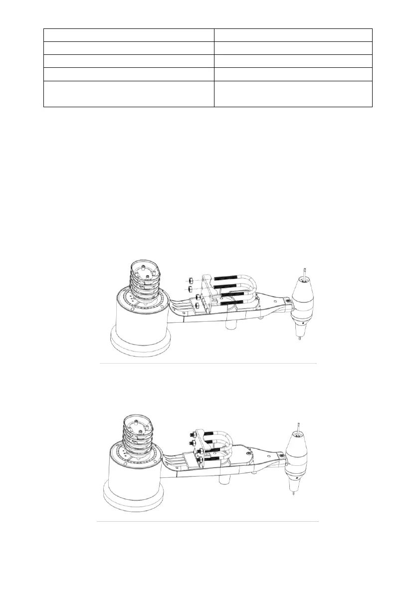
Installation of the U-bolts, which are in turn used to mount the sensor package
on a pole, requires installation of an included metal plate to receive the U-bolt
ends. The metal plate, visible in Figure 2, has four holes through which the
ends of the two U-Bolts will fit. The plate itself is inserted in a groove on the
bottom of the unit. Note that one side of the plate has a straight edge (which
goes into the groove), the other side is bent at a 90-degree angle and has a
curved profile (which will end up “hugging” the mounting pole). Once the
metal plate is inserted, remove nuts from the U-Bolts and insert both U-bolts
through the respective holes of the metal plate as shown in Figure 2.
Figure 2: U-Bolt installation
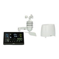
Loosely screw on the nuts on the ends of the U-bolts. You will tighten these
later during final mounting. Final assembly is shown in Figure 3.
Figure 3: U-Bolts and nuts installed