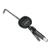
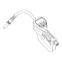
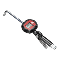
SER 3620 Electronic-Metered Control Valve
Revision (11-05) 8 Alemite LLC
Assembly
NOTE
: Prior to assembly, certain compo-
nents require lubrication. Refer to
Table 2
for details.
Control Valve Handle
NOTE
: Refer to
Figure 6
for a section
view of the control valve handle assembly.
1. Install Roll Pin (
31
) into Body (
30
) as required.
IMPORTANT: Lubricate O-Rings (
42
)
with grease prior to installation.
2. Install O-Rings (
42
) onto Cam (
43
).
3. Install the Cam assembly into the Body.
• Make sure to orient the Cam as shown in
Figure 5
.
4. Position Lever Assembly (
40
) onto the tabs of the
Cam.
• Make sure the safety does not interfere with the
Body.
5. Install Screws (
41
) that secure the Lever Assembly
to the Cam.
• Tighten the Screws securely.
6. Install Seal (
33
) [blunt end first] onto Push Rod (
32
).
7. Install Spring Support (
35
) into the small end of
Compression Spring (
36
).
8. Install Small Compression Spring (
34
) onto the
Spring Support.
9. Install the Push Rod and Seal assembly onto the
Spring Support.
10. Install the Compression Spring (with assembled
components) into the Body.
• Make sure the Push Rod seats properly on the
Cam.
11. Install Strainer (
37
) into the Compression Spring.
12. Install O-Ring (
38
) onto Swivel Assembly (
39
).
NOTE
: Swivel Assembly is under Spring pres-
sure during installation.
13. Screw the Swivel Assembly into the Body.
• Tighten the Swivel Assembly securely.
Transmission Fluid Filter
NOTE
: Refer to
Figure 5
for component iden-
tification.
1. Install Filter Tube (
26
) into Body (
25
).
2. Install O-Ring (
28
) onto Spring and Adapter Assembly
(
29
).
3. Install the small button of Stud (
27
) into the spring of the
Spring and Adapter Assembly.
4. Screw the Spring and Adapter Assembly into the Body.
• Tighten the Spring and Adapter Assembly securely.
Non-Drip Nozzle (Automatic w/ Manual Lock)
NOTE
: Refer to
Figure 3
for component iden-
tification.
1. Install Gasket (
22
) into Angle Body (
21
).
2. Install Washer (
23
) into Screw Assembly (
24
).
3. Thread the Screw Assembly into the Angle Body.
• Tighten the Screw Assembly securely.
4. Install O-Ring (
17
) onto Nozzle (
16
).
5. Install and seat V-Block (
18
) [concave first] onto the
pointed end of Stem (
19
).
6. Install the Stem assembly [point first] into the Nozzle.
7. Install Spring (
20
) into the Stem.
8. Screw the Nozzle assembly into Angle Body.
• Tighten the Nozzle securely.
Item No. Description Item No. Description
Clean Oil
17 O-Ring, 1/2 " ID x 5/8 " OD 28
O-Ring, 3/4 " ID x 15/16 " OD
38 O-Ring, 13/16 " ID x 1 " OD
Multi-Purpose Grease
42 O-Ring, 1/2 " ID x 11/16 " OD
Table 2
Lubricated Components
1-800-548-1191-http://www.partdeal.com-info@partdeal.com