Revision (10-04) 12 Alemite Corporation
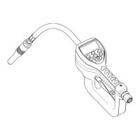
SER 3640 Electronic Preset Metered Control Valve
Assembly
NOTE
: Prior to assembly, certain compo-
nents require lubrication in clean oil. Refer
to
Table 3
for details.
Control Valve Assembly
Lever Mechanism
1. Install and hold Spring (
40
) onto Housing (
37
).
2. Position and hold Lever (
39
) onto the Housing.
3. Install Roll Pin (
38
) that secures the Lever and Spring
to the Housing.
Valve Mechanism
4. Install Valve (
30
) [with O-Ring (
28
), Back-Up Ring
(
29
), and Seal (
31
)] into the Housing.
5. Install Spring (
27
) into the Valve Assembly.
6. Install O-Ring (
26
) onto Nut (
24
).
7. Install Seal (
25
) into the Nut.
8. Screw the Nut into the Housing.
• Tighten the Nut securely.
9. Install Stop Pin (
20
) [long end first] into the Nut.
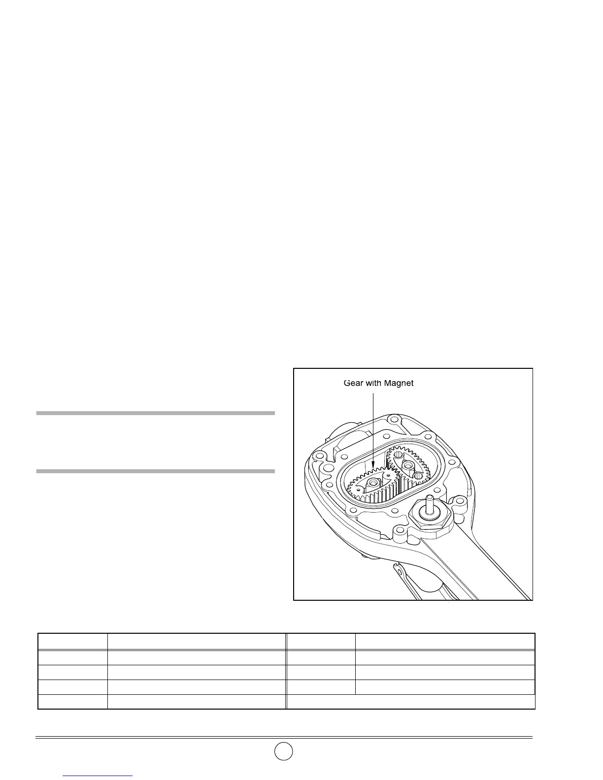
Metering Gears
CAUTION
Position the Gear with the magnets correctly in the
Housing. Meter will not function properly.
10. Install Gear (
36
) with the magnets into the Housing.
• Make sure to locate the Gear properly in the
Housing. See
Figure 9
.
11. Install additional Gear (
35
) into the Housing.
• Make sure this Gear engages the magnet Gear
perpendicularly.
IMPORTANT: Rotate the Gear assembly by
hand. Make sure the gear teeth are properly
engaged.
12. Install and seat O-Ring (
34
) into the oval groove in the
Housing.
13. Position Housing Cover (
33
) onto the Housing.
14. Install Screws (
32
) that secure the Housing Cover to
the Housing.
• Tighten the Screws in a crisscross pattern to 90 inch
pounds (10.2 Nm).
Circuit Board
15. Position the Housing assembly with Housing Cover
facing up.
16. Thread the wires from Circuit Board (
21
) through the
upper right hand openings in the Housing.
NOTE
: The battery terminal wire threads
through the larger opening.
17. Position the Circuit Board to the Housing.
18. Install Screws (
22
) that secure the Circuit Board
Assembly to the Housing Cover.
NOTE
: The lower right-hand screw contains
external tooth washer (
23
).
Item No. Description Item No. Description
12 O-Ring 31 Seal
25 Seal 34 O-Ring
26 O-Ring 50 O-Ring, 1/2 " ID x 5/8 " OD
28 O-Ring
Table 3
Components Lubricated in Clean Oil
Figure 9
Metering Gear
s
 Loading...