Alemite Corporation 13 Revision (10-04)
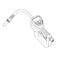
Electronic Preset Metered Control Valve SER 3640
Solenoid
19. Drop Detent Ball (
47
) into the hole in the Housing.
20. Screw Solenoid (
48
) into the Housing securely.
21. Carefully push the terminal connector [no polarity] onto the
Solenoid pins.
22. Install Keypad (
19
) into the holes of the Circuit Board
Assembly.
23. Install Top Case (
16
) onto the Housing.
24. Install Screws (
18
) that secure the Housing to the Top Case.
• Tighten the Screws securely.
25. Install one additional Screw (
17
) that secures the Top Case to
the Housing.
• Tighten the Screw securely.
26. Install and seat each Battery terminal onto Bottom Case (
41
).
• Make sure each terminal is fully seated.
27. Position the Bottom Case over the Lever and onto the
Housing.
• Route the wiring properly with no kinks.
NOTE
: The Bottom Case may contact the Sole-
noid connector. This is permissible.
28. Install Screws (
46
) that secure the Bottom Case to the
Housing.
• Tighten the Screws securely.
29. Insert the tab of Partition (
45
) into the Bottom Case.
30. Insert the tabs of Case Cover (
44
) into the Bottom Case and
over the Partition.
31. Install Screws (
43
) that secure the Case Cover and the
Partition to the Bottom Case.
• Tighten the Screws securely.
Battery Door
32. Position Battery Door (
42
) [with batteries] to the Bottom
Case.
33. Insert Screws (
43
) into the Battery Door.
• Tighten the Screws securely.
Swivel
34. Install Screen (
14
) and O-Ring (
15
) into Swivel (
13
).
NOTE
: O-Ring (
15
) is slightly smaller than O-Ring
(
12
).
35. Install O-Ring (
12
) onto the Swivel.
36. Screw the Swivel into the Valve’s Housing.
• Tighten the Swivel securely.
Extension and Nozzles
Non-Drip Nozzle (Automatic w/ Manual Lock)
NOTE
: Refer to
Figure 8
for compo-
nent identification.
1. Install Gasket (
55
) into Angle Body (
54
).
2. Install Washer (
56
) into Screw Assembly (
57
).
3. Thread the Screw Assembly into the Angle Body.
• Tighten the Screw Assembly securely.
4. Install O-Ring (
50
) onto Nozzle (
49
).
5. Install and seat V-Block (
51
) [heel end first] onto
Stem (
52
).
6. Install the Stem assembly into the Nozzle.
7. Install Spring (
53
) into the Stem.
8. Screw the Nozzle assembly into Angle Body.
• Tighten the Nozzle securely.
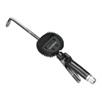
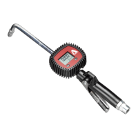
Extensions
1. Connect the components of the extension
assembly and tighten securely.
2. Screw the extension assembly into Control
Valve (
11
).
• Tighten the extension securely.
 Loading...