1. To turn the electronic lock clockwise to lock it after HDD/SD card and SIM card
are installed; otherwise, the device will not be powered on;
2. To ensure prolonged and stable operation, it is advised to have the device
horizontally installed and take waterproof measures;
3.It is recommended to install 3G/4G, GPS and WiFi antennas in a place where it
will not be blocked signal or be able to receive strong signal;
4.This product has 8 channels of alarm inputs, 1 channels of alarm output, one
RS485, and two RS232 extended externalports which allow connection
toappropriate devices according to requirements of vehicles;
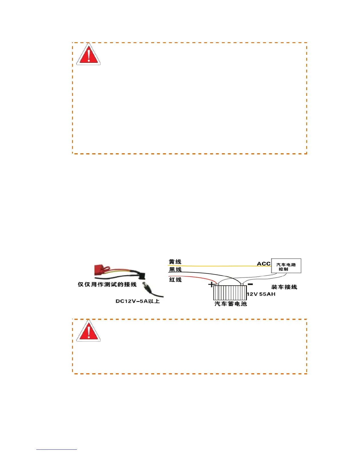
3. Power Connection
To connect the yellow cable of the power cord to ACC, the control circuit switch of the
vehicle, and the red and black ones are respectively connected to positive and negative electrode
of the vehicle power supply and then to vehicle MDVR. When testing the wiring condition,
twisting the red cable and yellow cable together and connect to the positive electrode, while the
black one is connected to the negative electrode.
Figure 2 Power Wiring Diagram
It is suggested that the MDVR power cable to be directly connected to the positive and negative
terminals of the vehicle battery cell (or the vehicle battery cell with fuse box). DO NOT connect
the MDVR power cable to any metal conductor subjects of the vehicle, which may influence
normal operation of the MDVR due to negative pulse; The power cable used for positive and
negative terminals shall have diameter of φ1.5mm or above.