5
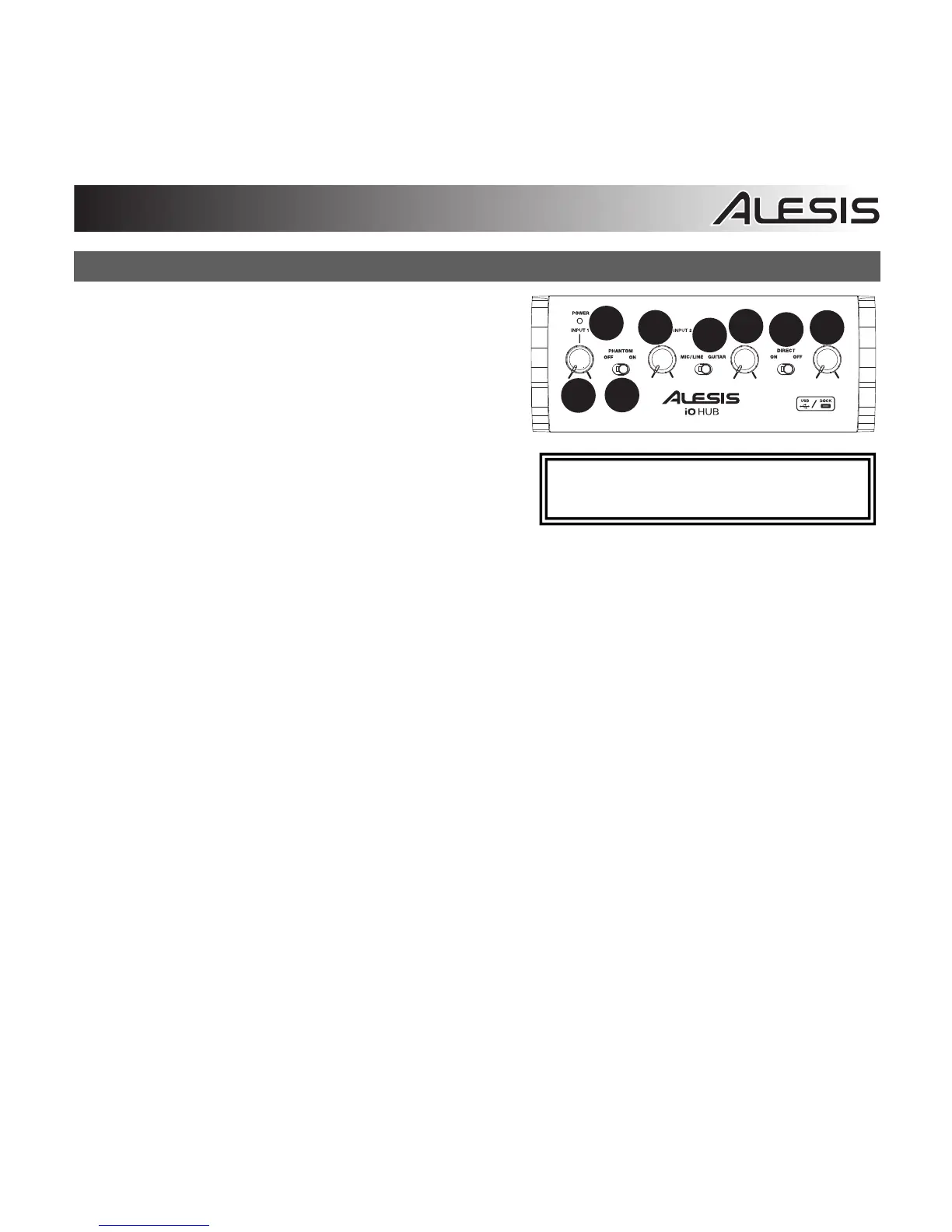
Front Panel
1. Power LED – This LED illuminates when iO Hub is
powered on.
2. Input 1 Gain – Adjusts the input signal level for
channel 1.
3. Phantom Power – This toggle switch activates and
deactivates phantom power for inputs 1/2. When
activated, phantom power supplies +48V to the
XLR mic inputs. A 9V battery must be connected to
iO Hub to activate phantom power when using iO
Hub with the Apple iPad Camera Connection Kit.
Please note that most dynamic microphones do not
require phantom power, while most condenser
microphones do. Consult your microphone's documentation to find out if it requires phantom power.
4. Input 2 Gain – Adjusts the input signal level for channel 2.
5. Mic/Line/Guitar switch – When this switch is in the "GUITAR" position, Input 2 will serve as a high-
impedance input for connecting guitar or bass instruments. When the switch is in the "MIC/LINE"
position, Input 2 will accept mic or line-level signals.
Note: When recording a guitar or bass with an active pickup, set iO Hub's MIC/LINE / GUITAR
SWITCH to "MIC/LINE." If your instrument uses a passive pickup, set the switch to "GUITAR."
6. Headphone Volume – Adjusts the signal level of the HEADPHONE OUTPUT.
7. Direct Switch – When this switch is set to ‘On’, you will be monitoring a 50/50 split mix of iO Hub’s
inputs and the computer’s USB output signal. When the switch is set to ‘Off’, you will be monitoring
only the USB signal from the computer.
8. Main Output Volume – Adjusts the signal level of the MAIN OUTPUTS.
NOTE: Turning on phantom power will
cause a momentary dropout in audio.
 Loading...