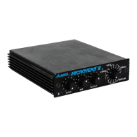
The Alesis MicroVerb/Microverb II (C1/C2) is a digital reverb unit designed to process analog audio signals, creating various reverb and time-based effects. This service manual covers both the MicroVerb and MicroVerb II, noting that they are virtually identical, with differences primarily in the algorithms programmed into the EPROM (U1), the digital clock rate, and the input filter values.
Function Description:
The core functionality of the MicroVerb/Microverb II involves converting analog audio signals into digital data, manipulating this data to create time delays, and then converting it back to analog. This process simulates natural reverb, as well as non-natural effects like reverse reverb and gated reverbs. The unit achieves this by slicing analog signals into segments, converting them to numeric values representing amplitude, and storing these values in a memory loop for playback. By varying the placement and amplitude of incoming samples, discrete time delays are achieved, which, when mixed and converted back to analog, produce the desired effects.
The device incorporates a sophisticated digital signal path centered around the DASP-16 ASIC (Application-Specific Integrated Circuit). This ASIC manages the digital signal processing, including analog-to-digital conversion (ADC) and digital-to-analog conversion (DAC). The input signal is first buffered, passed through input potentiometers, and then sent to a low-pass filter/buffer before being summed to mono. This summed signal then goes through an anti-aliasing filter before reaching the input sample and hold circuit, which consists of an analog switch, a sample capacitor, a buffer amplifier, and a comparator. Once the signal is digitized, the DASP-16 ASIC performs the necessary mathematical manipulations and stores the data in DRAM (Dynamic Random Access Memory). For output, the DAC within the DASP-16 outputs the processed left and right signals, which are then routed through output sample and hold circuits, low-pass filters, and buffers before reaching the mix and output potentiometers and finally the output jacks.
Important Technical Specifications:
- Power Supply: The unit operates from a 9 Volt A.C. adapter (Alesis P2 type). The internal power supply generates +12V, -12V, and +5V rails. The +12V rail uses a voltage doubler (C5, C6, D2, D4), a 7812 regulator (VR2), and filter capacitors (C10, C21). The -12V rail mirrors this with a voltage doubler (C4, C7, D3, D5), a 7912 regulator (VR3), and filter capacitors (C11, C22). The +5V rail uses a rectifier diode (D1), filter capacitors (C2, C3, C9), a 7805 regulator (VR1), and numerous 0.1uF bypass capacitors.
- ASIC: The DASP-16 ASIC (U2) is central to the digital processing, handling DRAM data bus (BDRAM0-15), DAC data outputs (DAC0-15), sample and hold circuit timing (SNHINH), A/D comparison input (ADCDATA), and the ASIC clock input (CLOCK). The clock input is 6MHz for MicroVerb and 8MHz for MicroVerb II.
- Memory: The unit utilizes a 27C64 EPROM (U1) for program storage and TMS4416 DRAMs (U3-6) for data storage during processing.
- Analog-to-Digital Conversion: The input sample and hold circuit, consisting of U9B, C20, U10, and U8, prepares the signal for the successive approximation process performed by the ASIC. This "divide and conquer" approach uses 12 comparisons to achieve a final 16-bit value.
- Overflow Detection: The DASP-16 ASIC provides an ERROR signal (pin 31) to indicate a math overflow condition, which activates the clip LED circuit.
- Shaft Encoder: A shaft encoder (S1) with associated logic (U13, U12, U11) is used for program switching, designed to prevent noise generation during changes.
- LED Indicator: A tri-color LED (L1) (driven by U14) indicates three states: orange for no signal input, green for signal present, and red for a math overflow condition.
Usage Features:
- Stereo Inputs/Outputs: The unit supports stereo inputs (J1, J2) and outputs (J3, J4), although it can operate monaurally (right input only).
- Input/Mix/Output Potentiometers: These controls allow users to adjust input levels, the wet/dry mix of the effect, and overall output levels.
- Program Selection: A shaft encoder (S1) allows users to select different reverb programs stored in the EPROM.
- Bypass Jack: The unit includes a bypass jack (J5) for routing the summed stereo signal directly, bypassing the effects processing.
Maintenance Features:
- Service Manual Purpose: This document is intended to assist service technicians with operation, maintenance, and repair. It complements the User Reference Manual by providing a complete description of functionality and serviceability.
- Authorized Service: Alesis explicitly states that only authorized Service Centers are permitted to perform service and repairs covered by an Alesis warranty. Unauthorized repairs void the warranty.
- Fuse Replacement: The product may use a replaceable fuse. Caution is advised to replace it only with the same type or equivalent recommended by the manufacturer to prevent fire or electrocution.
- Internal Battery: If an internal battery is present, caution is advised for replacement. It should only be replaced with the same or equivalent type, and used batteries must be disposed of according to manufacturer instructions.
- Component Specific Corrections/Updates:
- C13, C16, C23, C32: Blue monoblock capacitors in these positions should be replaced with 0.1µF CerDisk or Film capacitors due to excessive leakage. Faulty C13 causes the LED to always show green (input signal present). Faulty C16 causes the LED to always show red (overflow). Faulty C23 results in no wet effects output. Faulty C32 causes a distorted wet signal due to an unstable +5V rail at U9.
- C20: Large Mylar capacitors should be replaced with film capacitors due to excessive leakage, as failure can cause distorted wet signals.
- Potentiometers: If any of the input, mix, or output potentiometers are "scratchy," it's recommended to replace all three. The front panel should be reattached before soldering new potentiometers to prevent misalignment.
- Goldstar 4053s (U9): These devices have been found unreliable and should be replaced with Phillips CD4053s to prevent extreme D.C. offset in the SAR output of the DAC.
- Goldstar 7404s (U11): These devices have also been found unreliable and should be replaced with TI 74HC14s to prevent "Pops" when switching programs.
- Beige Power Supply Jacks: Older beige power supply jacks should be replaced with newer black jacks due to a tendency for the center pin to break.
- Troubleshooting Guide: The manual includes a comprehensive troubleshooting table linking described symptoms (e.g., unit dead, no effects, distorted effects, noise when switching, intermittent effects) to possible causes (e.g., faulty power supply, leaky capacitors, faulty ASIC, faulty ICs, dirty contacts) and recommended solutions (e.g., replace and retest, troubleshoot and repair as necessary).
- Test Procedures: Simple test procedures are outlined, including using a clean audio source, listening for distortion, moving potentiometers through their full range, checking shaft encoder function, listening for excessive noise, and physically shaking the unit to check for loose parts.