4
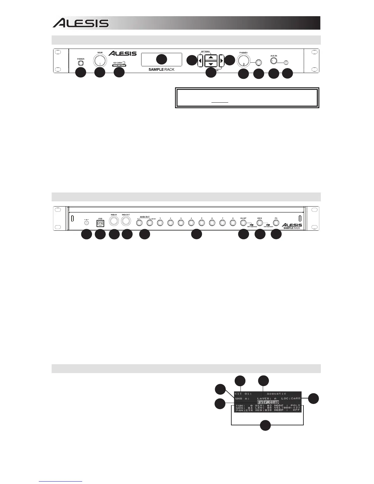
Top Panel Features
1. Power Switch - Press this button to turn
SampleRack on. Hold this button for two
seconds and release to turn SampleRack
off.
2. Main Volume - Adjusts the overall volume level for the Main Out.
3. SD Card Slot - Insert a standard SD card (not included) containing .WAV samples into this slot.
4. LCD - Displays the current parameters and other operations.
5. Cursor Left - Press this button to decrease the value of a parameter.
6. Cursor Up/Down - Press these buttons to move up and down through the available parameters or menu
options.
7. Cursor Right - Press this button to increase the value of a parameter or enter a submenu.
8. Phones Volume - Adjusts the overall volume level for the Phones Out.
9. Phones Out - Connect a pair of 1/4" headphones to this output.
10. Aux In Volume - Adjusts the level of the device connected to the Aux Input.
11. Aux In - Connect a phone, CD player, or media player to this input using a stereo 1/8" cable.
Rear Panel Features
1. DC Input - Connect the included power adapter here, then connect the adapter to wall power.
2. USB/MIDI Port - Connect SampleRack to a computer to send and receive MIDI data or load samples to the SD
card.
3. MIDI In - Use a standard five-pin MIDI cable to connect this input to the MIDI OUT of an external MIDI device.
4. MIDI Out - Use a standard five-pin MIDI cable to connect this output to the MIDI IN of an external MIDI device.
5. Main Out - Use standard 1/4" cables to connect this output to a speaker or amplifier system. (For mono sound,
connect a cable only to the Left output.)
6. Trigger Inputs - Connect the triggers of your drum kit to the appropriate inputs here. Please note that dual-
zone pads or cymbals (e.g., a drum with head and rim zones or a cymbal with bow and bell or choke sounds)
will require TRS cables to trigger both zones.
7. Hi-Hat Input - Connect a Hi-Hat pedal here using a 1/4" TS cable to use this input to control the position of a
Hi-Hat while playing. Select "SWITCH" if you are using a standard footswitch. Select "VARIABLE" if you are
using a variable hi-hat pedal.
We recommend using the Alesis DMHat Pedal with SampleRack.
8. Kick Pedal Input - Connect a kick trigger or footswitch here using a 1/4" TS cable to use this input as a kick
trigger while playing. Select "SWITCH" if you are using a footswitch or switch trigger. Select "TRIGGER" if you
are using a velocity-sensitive pedal or velocity-sensitive kick trigger.
9. Footswitch Input - Connect a standard 1/4" TS single-button or 1/4" TRS dual-button footswitch here to
control functions assigned in the Footswitch options menu.
LCD Screen
1. Kit - Displays the name of the kit that is currently being
edited.
2. Sample Location - Displays the location of the sample
assigned to the velocity layer being edited.
3. Sample Name - Displays the sample that is currently
assigned to the velocity layer of the trigger location being
edited.
4. Trigger Location - Displays the trigger location that is
currently being edited.
5. Velocity Layer - Displays the velocity layer of the trigger location that is currently being edited.
6. Other Parameters - Displays the tuning, sensitivity, panning, reverb, level, MIDI Note, mode, and mute group
parameters of the velocity layer that is currently being edited.
WARNING: Put on your headphones or turn on your
speakers only AFTER turning on SampleRack.
4