5 Mainten ance
Read the instructions carefully. The items refer to the parts list and service kits section.
Handle scrap correctly.
: Relates to the shaft seal.
5.4 Assembly of pump/single shaft seal
S
t
e
p
1
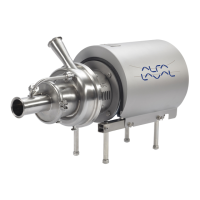
1. Remove spring (13
).
N
O
T
E
!
Make sure that O-
ring (15) has maximum clearance from the
sealing surface.
If change from d
ouble mechanical shaft seal to single shaft seal the
shaft needs to be adjusted. see Section 5.7 Adjustment of shaft
(LKH-5) and Section 5.8 Adjustment of shaft (LKH-10 to -90).
3000-0239
Max
S
t
e
p
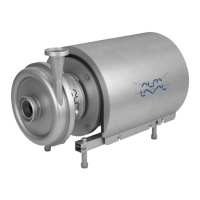
2
1. Refit spring (13) on rotating seal ring (14).
2. Fit the spring and the rotating seal ring on drive ring (10).
C
A
U
T
I
O
N
Ensure that the driver on the drive ring enters the notch in the
rotating se
al ring.
3000-0240
S
t
e
p
3
Fit the complete shaft seal on stub shaft (7).
N
O
T
E
!
Make sure that Connex pin (8) on the stub shaft enters the notch
in drive ring (10).
3000-0241
S
t
e
p
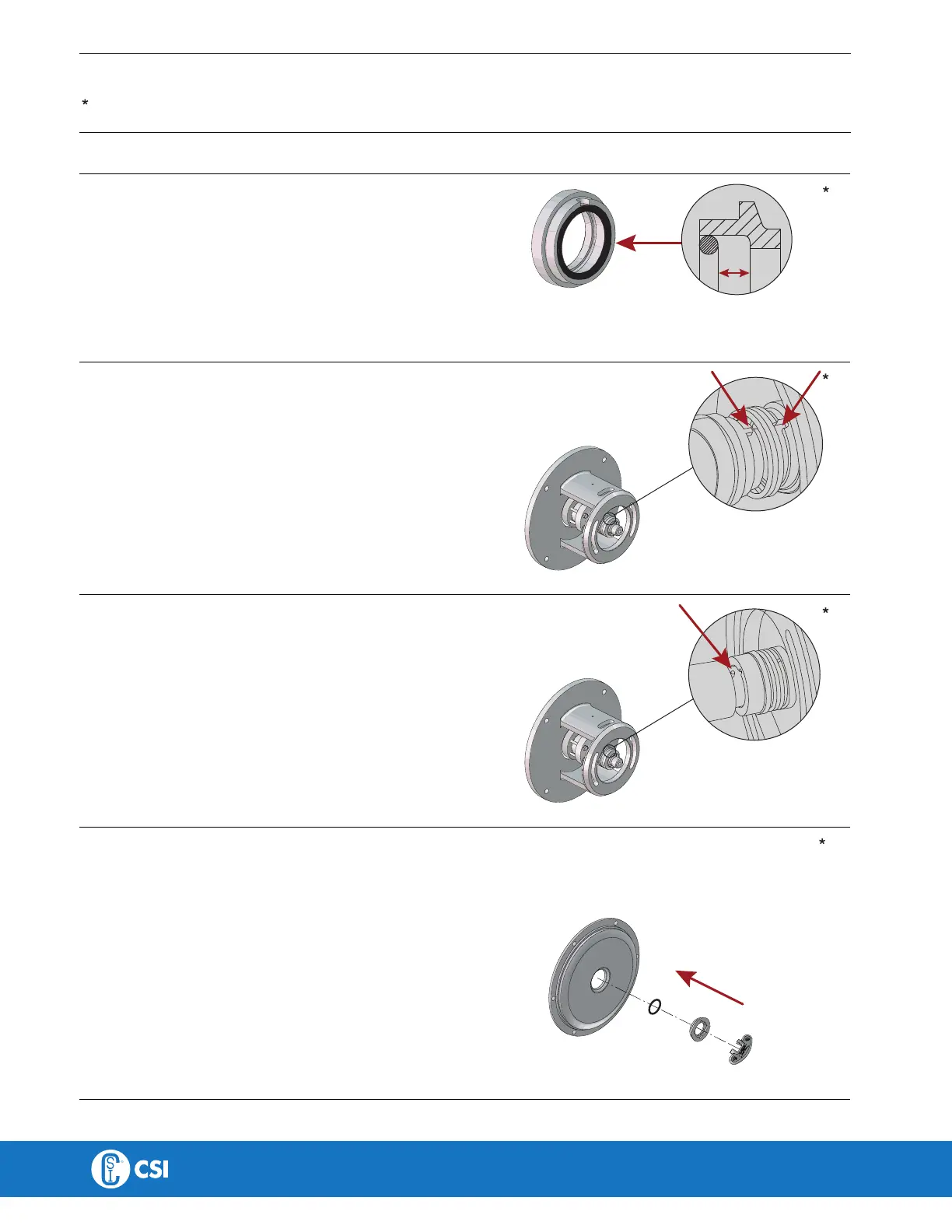
4
1. Fit O-r
ing (12) on stationary seal ring (11) and lubricate.
2. Screw
the stationary seal ring into back plate (25).
C
A
U
T
I
O
N
Only t
ighten by hand to avoid deforming the stationary seal ring.
(Max. 7 Nm/5 lbf-ft)
*) Use the tool supplied. Left hand thread!
3000-0242
*
CONTACT CSI FOR MORE INFORMATION | CSIDESIGNS.COM | SALES@CSIDESIGNS.COM | 417.831.1411