5 Mainten ance
Read the instructions carefully. The items refer to the parts list and service kits section.
Lubricate the rubber seals before fitting them.
: Relates to the shaft seal.
S
t
e
p
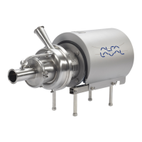
4
1. F
o
r
t
h
e
d
o
u
b
l
e
m
e
c
h
a
n
i
c
a
l
s
h
a
f
t
s
e
a
l
:
Fit d rive ring (52) on stub shaft (7).
2. Fit back plate (25), washers (21) and nuts (20) and tighten.
3000-0256
S
t
e
p
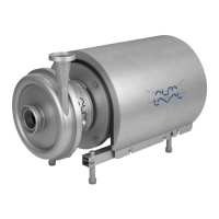
5
1. Fit impeller
(27) on stub shaft (7).
2. Ensure that t
he clearance between the impeller and back plate
(25) is corr
ect: 0.5mm(0.02inch)forLKH-10to60and1.0
mm (0.039 in
ch) for LKH-70 to -90.
3. Tighten scr
ews (6) evenly until the stub shaft (7) cannot move
on the moto
r shaft.
The clearance can be adjusted by knocking gently with a plastic
hammer.
*) LKH-10 to -60 = 0.5 mm (0.02 inch)
LKH-70 to -90 = 1.0 mm (0.039 inch)
3000-0257
*
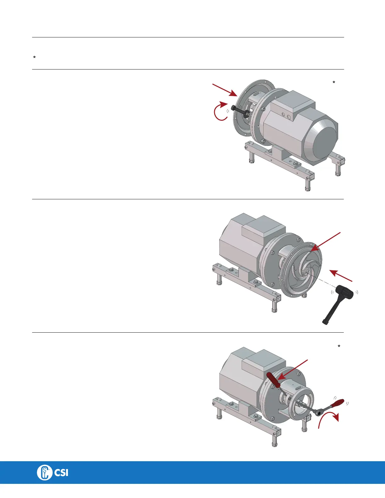
S
t
e
p
6
1. Remove impeller (27), back plate (25) and drive ring (52).
2. Tighten screws (6) evenly to 15 Nm (11 lbf-ft).
Tighten screws diagonally.
*) 15Nm (11 lbf-ft)
Counterhol d with a screwdriver
3000-0262
*
CONTACT CSI FOR MORE INFORMATION | CSIDESIGNS.COM | SALES@CSIDESIGNS.COM | 417.831.1411
 Loading...