3.5 Electrical installation, IO-link
1
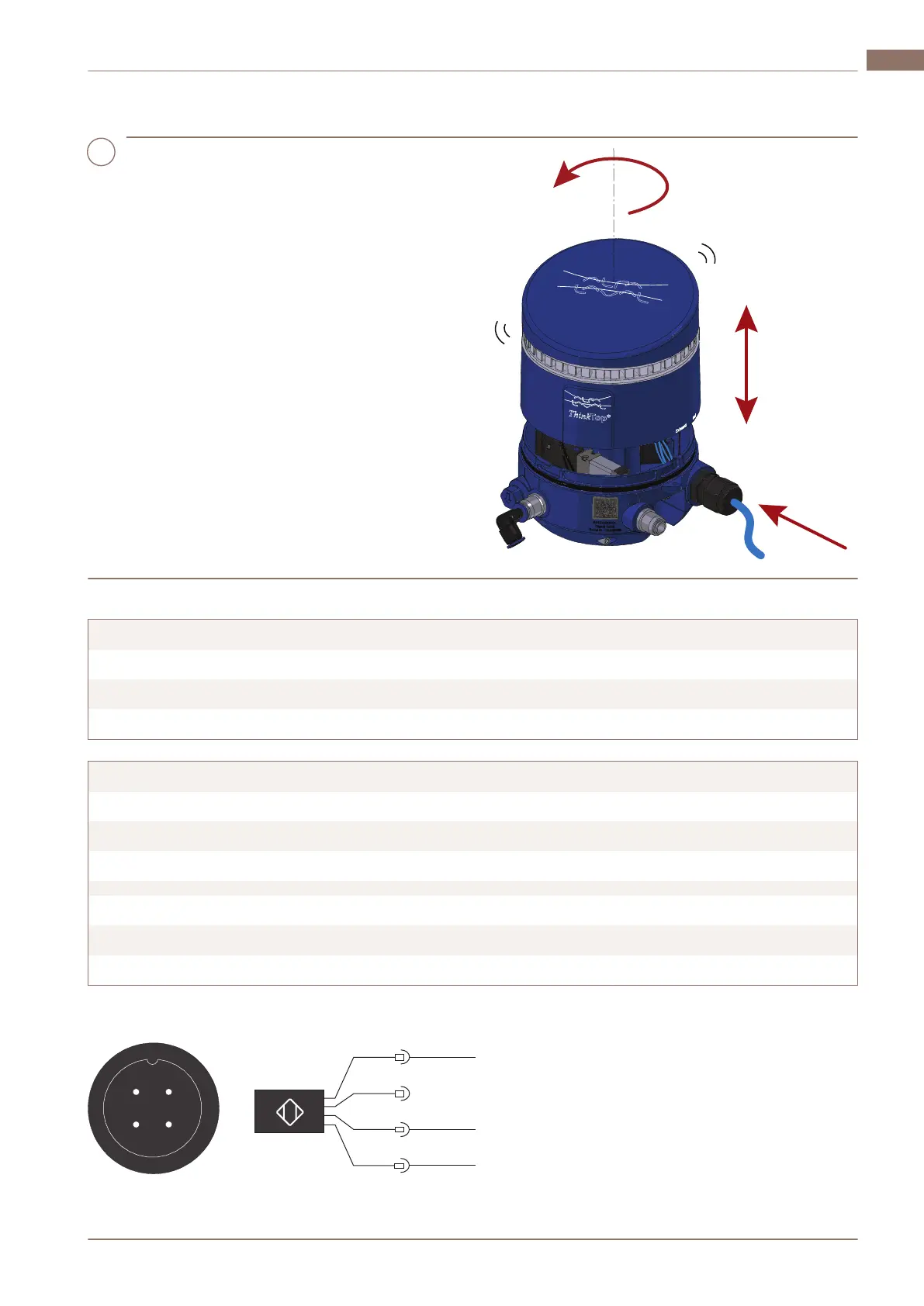
a) Remove the top cover by turning it
counter clockwise and then lifting it
upwards.
b) Fit the cable to the M12 connector and
tighten it using a 14 mm wrench (0.6...1.5
Nm).
c) Put the top cover back in place.
d) Turn on the power supply.
If installed correctly, the light guide flashes
green.
Wiring diagrams
Terminals V50 IO-Link
1 Power supply L+ 24V (brown)
2 Power supply L- GND (blue)
3 Signal IO-Link (black)
Terminals V70 IO-Link
1 Power supply L+ 24V (brown)
2 Power supply L- GND (blue)
3 Signal IO-Link (black)
1 Seat lift sensor Supply (brown)
2 Seat lift sensor GND (blue)
3 Seat lift sensor Signal (black)
M12 option (4-pin A-coded plug):
BN
BK
OUT1
BU
L
+
L -
2066-0055
1
4
2
3
1
3
4
2
200000549-1-EN-GB 15
Installation 3 EN
www.sks-online.com
www.sks-webshop.com
 Loading...