Do you have a question about the Alfa Laval ARC series and is the answer not in the manual?
Key information and warnings to read before using the valve for safe operation.
Explanation of warning symbols used in the manual for hazard identification.
Detailed safety instructions for installation, operation, and maintenance to prevent injury.
Procedures for checking valve components upon delivery and inspecting for transport damage.
Instructions for proper valve mounting, orientation, and connection of air supply.
Guidance on welding the valve body, including required clearances and post-welding checks.
Steps for installing the optional oil damper to mitigate water hammer effects.
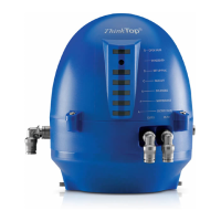
Instructions for installing optional top units and indication equipment.
Guidelines for the correct operation of the valve, including lubrication and vacuum usage.
Identification and repair of common problems like leakage, valve jerk, and water hammer.
Steps for cleaning the valve, including safety precautions for caustic agents and sterilization.
Routine checks, spare parts recommendations, and general upkeep for the valve.
Step-by-step guide for disassembling the valve components for service or repair.
Detailed procedures for reassembling the valve after maintenance.
Instructions for taking apart the valve actuator for inspection or repair.
Steps for correctly reassembling the valve actuator.
Key technical specifications including pressure, temperature, materials, and air requirements.
Itemized list of components for the ARC with reduced stroke, stop valve.
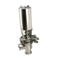
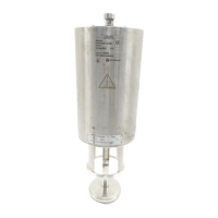
Visual representation of the ARC stop valve components for identification.
Itemized list of components for the ARC with reduced stroke, change-over valve.
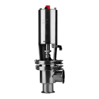
Visual representation of the ARC change-over valve components for identification.
Itemized list of components for the optional oil damper.
Visual representation of the optional oil damper components for identification.
| Supply voltage | 24 VDC |
|---|---|
| Enclosure class | IP65 |
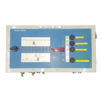
| Type | Control Unit |
| Series | ARC |
| Storage Temperature | -40 to +70 °C |
| Humidity | Max. 95% relative humidity, non-condensing |