Do you have a question about the Alfa Laval ThinkTop Digital 8 and is the answer not in the manual?
General important information and warnings for safe operation.
Explanation of warning signs used in the manual.
Specific safety precautions for installation and maintenance.
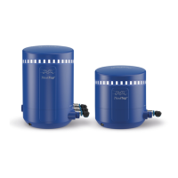
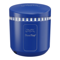
Explanation of the digital aspects and functionality of the ThinkTop®.
Technical details for the ThinkTop® interface with PLC systems.
Description of the "No Touch" sensor system for valve stem position detection.
Details on tolerance programmes, self-adjustment, and maintenance monitoring.
Specific technical parameters of the sensor system.
Information on terminals, power supply, and polarity selection.
Information on feedback signals and the use of external sensors.
Step-by-step guide for installing the ThinkTop® on air actuators.
Instructions for installing the ThinkTop® on Series 700 valves.
Details on how to connect the air tubes to the ThinkTop® unit.
Instructions for internal electrical connections of the ThinkTop®.
Examples illustrating how to connect power supplies to the system.
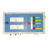
Diagram and steps for setting up the ThinkTop® using an IR keypad.
Diagram and steps for setting up the ThinkTop® using local 'I' and 'II' keys.
Guide to diagnosing faults using LED indications and troubleshooting steps.
Step-by-step instructions for dismantling the ThinkTop® unit.
Step-by-step instructions for assembling the ThinkTop® unit.
Procedures for dismantling and assembling Series 700 valves.
Parts list and exploded drawing for the Digital 8-30 VDC PNP/NPN model.
Parts list and exploded drawing for Series 700 valves.
| Supply voltage | 24 V DC |
|---|---|
| Number of sensors | Up to 3 |
| Valve position feedback | Yes |
| Communication Protocols | Ethernet/IP |
| Operating temperature | -20°C to +70 °C |
| Protection Class | IP66 |