18
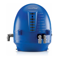
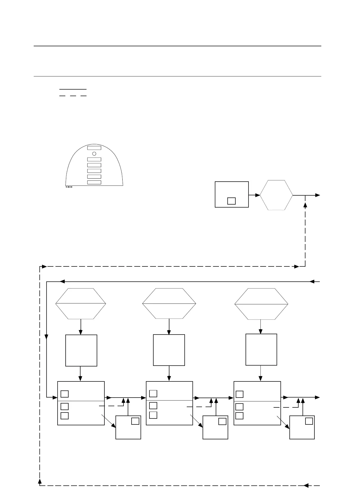
5. Setup diagram5.1 ThinkTop
®
setup utilising IR keypad
EnterEnter
EnterEnter
Enter
Set-up SequenceSet-up Sequence
Set-up SequenceSet-up Sequence
Set-up Sequence
00
00
0
LED D steady,
then flashing
Set Open PositionSet Open Position
Set Open PositionSet Open Position
Set Open Position
00
00
0
BypassBypass
BypassBypass
Bypass
Move to next step
11
11
1
Store PositionStore Position
Store PositionStore Position
Store Position
55
55
5
Disable functionDisable function
Disable functionDisable function
Disable function
(LED B flashing)
Actuate theActuate the
Actuate theActuate the
Actuate the
valve tovalve to
valve tovalve to
valve to
open positionopen position
open positionopen position
open position
Set Upper Seat LiftSet Upper Seat Lift
Set Upper Seat LiftSet Upper Seat Lift
Set Upper Seat Lift
00
00
0
BypassBypass
BypassBypass
Bypass
Move to next step
11
11
1
Store PositionStore Position
Store PositionStore Position
Store Position
55
55
5
Disable functionDisable function
Disable functionDisable function
Disable function
(LED B flashing)
LED D, C, B steadyLED D, C, B steady
LED D, C, B steadyLED D, C, B steady
LED D, C, B steady
if
upper seat lift
enabled
LED D, C steadyLED D, C steady
LED D, C steadyLED D, C steady
LED D, C steady,
B flashing B flashing
B flashing B flashing
B flashing
if
upper seat lift
disabled
Actuate theActuate the
Actuate theActuate the
Actuate the
valve tovalve to
valve tovalve to
valve to
upper seat liftupper seat lift
upper seat liftupper seat lift
upper seat lift
Press 0Press 0
Press 0Press 0
Press 0
to bypassto bypass
to bypassto bypass
to bypass
move tomove to
move tomove to
move to
next stepnext step
next stepnext step
next step
Press 0Press 0
Press 0Press 0
Press 0
to bypassto bypass
to bypassto bypass
to bypass
move tomove to
move tomove to
move to
next stepnext step
next stepnext step
next step
LED D, C, A steadyLED D, C, A steady
LED D, C, A steadyLED D, C, A steady
LED D, C, A steady
if
lower seat lift
enabled
LED D, C steadyLED D, C steady
LED D, C steadyLED D, C steady
LED D, C steady,
A flashingA flashing
A flashingA flashing
A flashing
if
lower seat lift
disabled
Set Lower Seat LiftSet Lower Seat Lift
Set Lower Seat LiftSet Lower Seat Lift
Set Lower Seat Lift
00
00
0
BypassBypass
BypassBypass
Bypass
Move to next step
11
11
1
Store PositionStore Position
Store PositionStore Position
Store Position
55
55
5
Disable functionDisable function
Disable functionDisable function
Disable function
(LED A flashing)
Actuate theActuate the
Actuate theActuate the
Actuate the
valve tovalve to
valve tovalve to
valve to
lower seat liftlower seat lift
lower seat liftlower seat lift
lower seat lift
LED D, B steadyLED D, B steady
LED D, B steadyLED D, B steady
LED D, B steady
if
open position
enabled
LED D steadyLED D steady
LED D steadyLED D steady
LED D steady,
B flashingB flashing
B flashingB flashing
B flashing
if
open position
disabled
Step 4Step 4
Step 4Step 4
Step 4
Step 5Step 5
Step 5Step 5
Step 5
Step 6Step 6
Step 6Step 6
Step 6
See opposite pageSee opposite page
See opposite pageSee opposite page
See opposite page
See opposite pageSee opposite page
See opposite pageSee opposite page
See opposite page
See opposite pageSee opposite page
See opposite pageSee opposite page
See opposite page
See opposite pageSee opposite page
See opposite pageSee opposite page
See opposite page
Press 0Press 0
Press 0Press 0
Press 0
to bypassto bypass
to bypassto bypass
to bypass
move tomove to
move tomove to
move to
next stepnext step
next stepnext step
next step
Notes: O - Scroll across, no change
- Notes Requires Key Function
- - Notes Automatic Progress as Indicated
General: 1. Flashing IND means no value set.
Steady IND means value set as shown.
2. Default is: Step 2, Type 0 (+/- 5 mm)
Step 3-8 disabled
3. Lamp Status Shown in [ ]
4. [D] IND active during set-up.
- Flashing in step 1,
- Steady in all other steps.
or during operations, error condition
- Steady showing hardware fault
- Flashing showing software fault
5. Timeout: A 60 second time-out is started as soon as any button(s) are released.
If no button is pressed during the time-out time, go to normal condition (cancel & exit).
6. SRC/ARC valves: Self-adjust (step 7) must be activated. If you choose NOT to use the
self-adjustment programme, Alfa Laval recommends to use the valve type 4 (step 2), instead of
type 1 (bigger tolerances).
LED B "Open valve" (Yellow)
IR-Receiver
LED D "Setup/Internal fault" (Red)
LED C "Seat-lift 1/2" (Yellow)
LED E "Solenoid valves" (Green)
LED F "Maintenance" (Orange)
LED A "Closed valve" (Yellow)
ThinkTop
®
Visual Indications LED Indications
 Loading...