3 Installation
Study the instructions carefully.
The valve is supplied as separate parts to facilitate the welding.
The items refer to the parts list and service kits section.
Check the valve for smooth operation after welding.
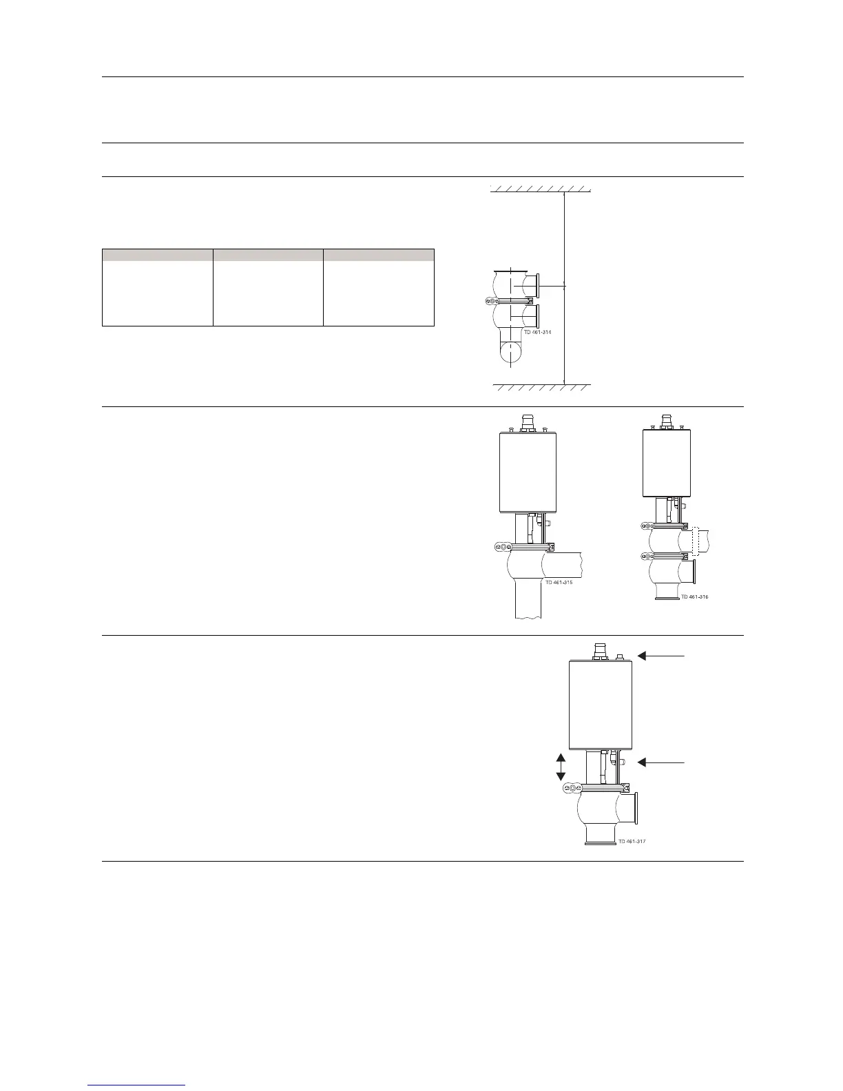
3.3 Welding
Step 1
Always install valves with more than one valve body so that the
seals between the valve bodies can be replaced. Do not weld
more than one valve body into the system.
Valve size
A (inch) B (inch)
1” * 24.8
1 ½”*27.6
2” * 29.5
2 ½”*29.1
3” * 31.5
4” * 31.1
* Depending on body combination and piping solution.
B (incl. top unit)
A*
Step 2
Assemble the valve in accordance with the steps on page 22.
Pay special attention to the warnings!
Step 3
Pre-use check:
1. Supply compressed air to the actuator.
2. Open and close the valve several times to ensure that it
operates smoothly.
Pay special attention to the warnings!
Air
Air
Open/close!
11
 Loading...