13
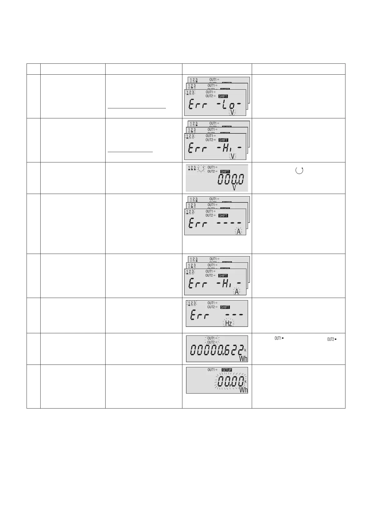
9. DIAGNOSTIC FUNCTIONS
The diagnostic functions allow to check if there is any error in the instrument connections or one of the
measured voltage and/or current is out of range; the instrument can display some symbols with a specific
meaning. Hereafter the description of the available diagnosis:
N. Function Condition Display Description
1 Under Voltage V
L-N
‹ 75% of nominal
value
See notes *, **, ***
The V
L-N
page, relating to the
out-of-range phase, displays
an error message as shown.
The 1,2,3 and V symbols are
flashing.
2 Over Voltage V
L-N
› 120% of nominal
value
See notes *, **
The V
L-N
page, relating to the
out-of-range phase, displays
an error message as shown.
The 1,2,3 and V symbols are
flashing.
3 Wrong phase order The phase sequence is
not 1-2-3.
The symbol " " flashes.
4 Wrong current
wiring (inverted
current sense)
NOTE: the error is
displayed only in case of
monodirectional type.
In case of bidirectional
instrument, "-" sign is
displayed before the
values.
The phase current page,
relating to the out-of-range
phase, displays an error
message as shown. The 1,2,3
and A symbols are flashing.
5 Over current A › 120% of fullscale The phase current page, rela-
ting to the out-of-range phase,
displays an error message
as shown. The 1,2,3 and A
symbols are flashing.
6 Frequency out of
range
65 Hz ‹ f ‹ 45 Hz The frequency page displays
an error message as shown.
The 1,2,3 and Hz symbols are
flashing.
7 Pulse emission
(frequency too
high)
f
PULSE
› 3pulses / second
The " " and / or " "
symbol flashes.
8 The pulse
weight of digital
output cannot
be automatically
modified
The new selected CT
value is too high to
mantain the old pulse
value.
In programming mode the
pulse weight flashes.
* : Nominal value depends on the instrument model.
** : In case of 3 phases, 3wires, 3 CTs model, the threshold values are referred to V
L-L
voltages.
*** : On 3 phases, 3wires, 3 CTs model, the first diagnostic case "Under Voltage" has a second meaning:
i.e. the instrument serial communication is not possible.
 Loading...