EasyManuals Logo

Algodue ELETTRONICA UPT210 User Manual

Algodue ELETTRONICA UPT210
20 pages
To Next Page IconTo Next Page
To Previous Page IconTo Previous Page
Page #7 background imageLoading...
Page #7 background image
7
25A INSTRUMENT VERSION
WARNING!
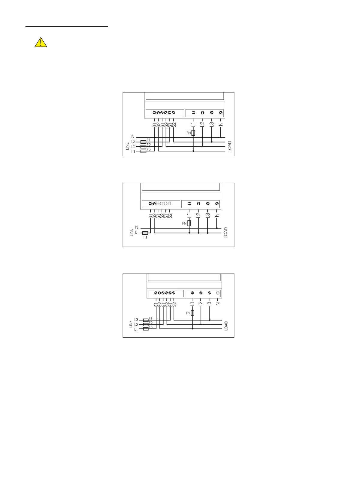
Every wiring diagram must be provided with fuses (F1, F2, F3, FN) or another similar
protection as indicated in the picture. The F1/F2/F3 value will depend on the load. The FN
value is 100mA and it is required only when the instrument is provided with serial port.
WIRING DIAGRAM: 3 PHASES - 4 WIRES / 3 CURRENT TRANSFORMERS (3.4.3) connection
WIRING DIAGRAM: 1 PHASE (1ph) connection
WIRING DIAGRAM: 3 PHASES - 3 WIRES / 3 CURRENT TRANSFORMERS (3.3.3) connection (on request)

Questions and Answers:

Question and Answer IconNeed help?

Do you have a question about the Algodue ELETTRONICA UPT210 and is the answer not in the manual?

Algodue ELETTRONICA UPT210 Specifications

General IconGeneral
BrandAlgodue ELETTRONICA
ModelUPT210
CategoryTransducer
LanguageEnglish