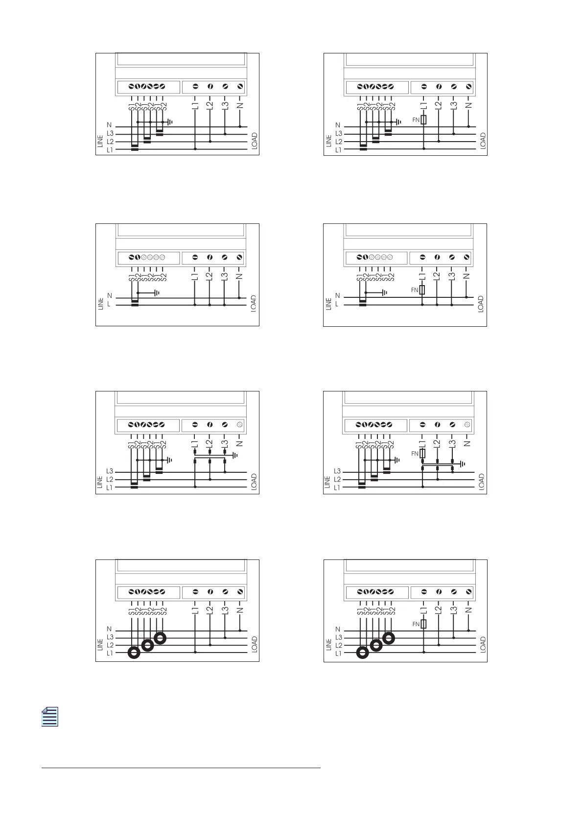
6
WIRING DIAGRAM: 3 PHASES - 4 WIRES / 3 CURRENT TRANSFORMERS (3.4.3) connection
Pict. A: direct connection (3.4.3) Pict. B: direct connection (3.4.3) *
with serial communication port
WIRING DIAGRAM: 1 PHASE (1ph) connection
Pict. C: direct connection (1ph) Pict. D: direct connection (1ph) *
with serial communication port
WIRING DIAGRAM: 3 PHASES - 3 WIRES / 3 CURRENT TRANSFORMERS (3.3.3) connection (on request)
Pict. E: connection with VT (3.3.3) Pict. F: connection with VT (3.3.3) *
with serial communication port
WIRING DIAGRAM: 3 PHASES - 4 WIRES / 3 ROGOWSKI COILS (3.4.3) connection (on request)
Pict. G: direct connection (3.4.3) Pict. H: direct connection (3.4.3) *
with serial communication port
NOTE. In case of Rogowski coils, please check that YELLOW cable edge is connected to S1 (signal)
and the WHITE cable edge is connected to S2 (common).
* FN=100mAT T type - only with serial communication port
 Loading...