4
3
5 6
1
PNP NPN
A COM OUT1
B OUT1 OUT2
C OUT2 COM
A B C + -
2
4
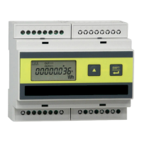
7. ELECTRICAL CONNECTIONS
The instrument must be installed according to the following order:
WARNING!
Before making any connection, check that the
control panel main switch is OFF.
Digital outputs. See section 7.21.
19÷60V2. d c power supply (option on request). See section 7.4
Serial port (option on request). See section 7.13.
FTT-10 port (LONBUS option on request)4.
Current inputs. See section 7.35.
Voltage inputs. See section 7.36.
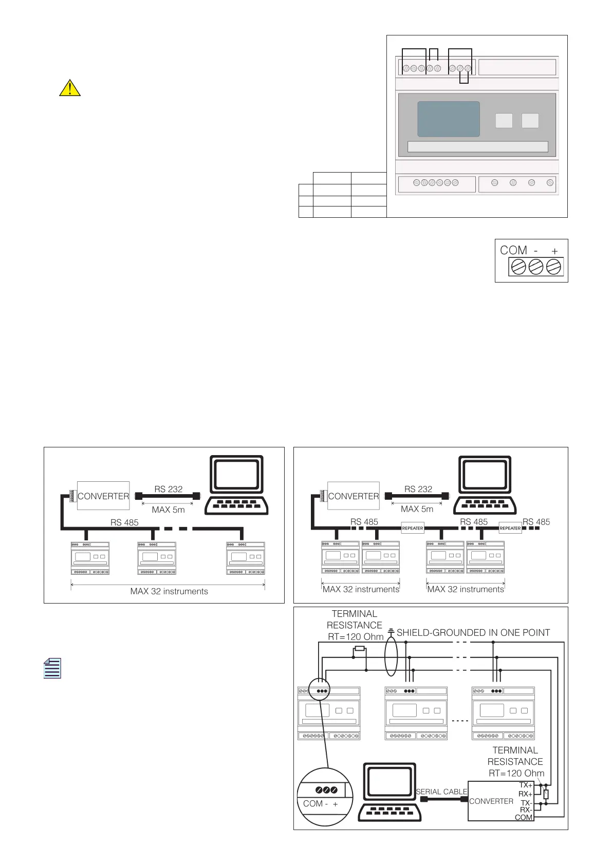
7.1 SERIAL COMMUNICATION PORT (optional)
The serial port allows PC connection. The RS485 communication port is supplied.
7.1.1 RS485
The easiest and cheapest way to connect different measuring devices in a network is the RS485 serial line.
The RS485 standard interface allows a multi-point connection. Between PC and the network, it is required a
Serial RS232 to RS485 Converter. If more than 32 instruments are to be connected, insert a signal repeater.
Each repeater can manage up to 32 instruments. For the connection among the different modules, use a
cable with a twisted pair and a third wire. The type of connection shown in the following picture uses the
third conductor to ensure that all the devices on the network have the same reference level and improve
the reliability of communication. When there are strong electromagnetic disturbances, which may affect
communication, a shielded cable should be used. The Rt termination resistance must be installed on the
PC and the last instrument connected along the line. Thanks to these resistances, the reflected signal
along the line is reduced.
For a typical telephone pair, Rt can have values
from 120 to 150 Ohm.
NOTE. The value of each resistance must
not be lower than 120 Ohm in order to avoid
an overload of line drivers.
The max. recommended distance for a connection
is 1200 m at 9600 Baud. For longer distances,
lower baud rates or low-attenuation cables or
signal repeaters are needed.
 Loading...