2
www.observint.com
4. Slide the tab away from the lip on the bottom of the shroud and turret assembly, and then
separate the shroud and turret assembly from the adapter plate.
Step 3. Install a microSD card (optional)
Install a microSD card in the camera to save alarm and status information locally, and to locally save
video and captures les. Refer to the Specications section for storage card requirements. The storage
card can be a
microSD/SDHC/SDXC card, up to 128GB. NOTE: The card can be formatted within the
camera, if necessary.
To install the card:
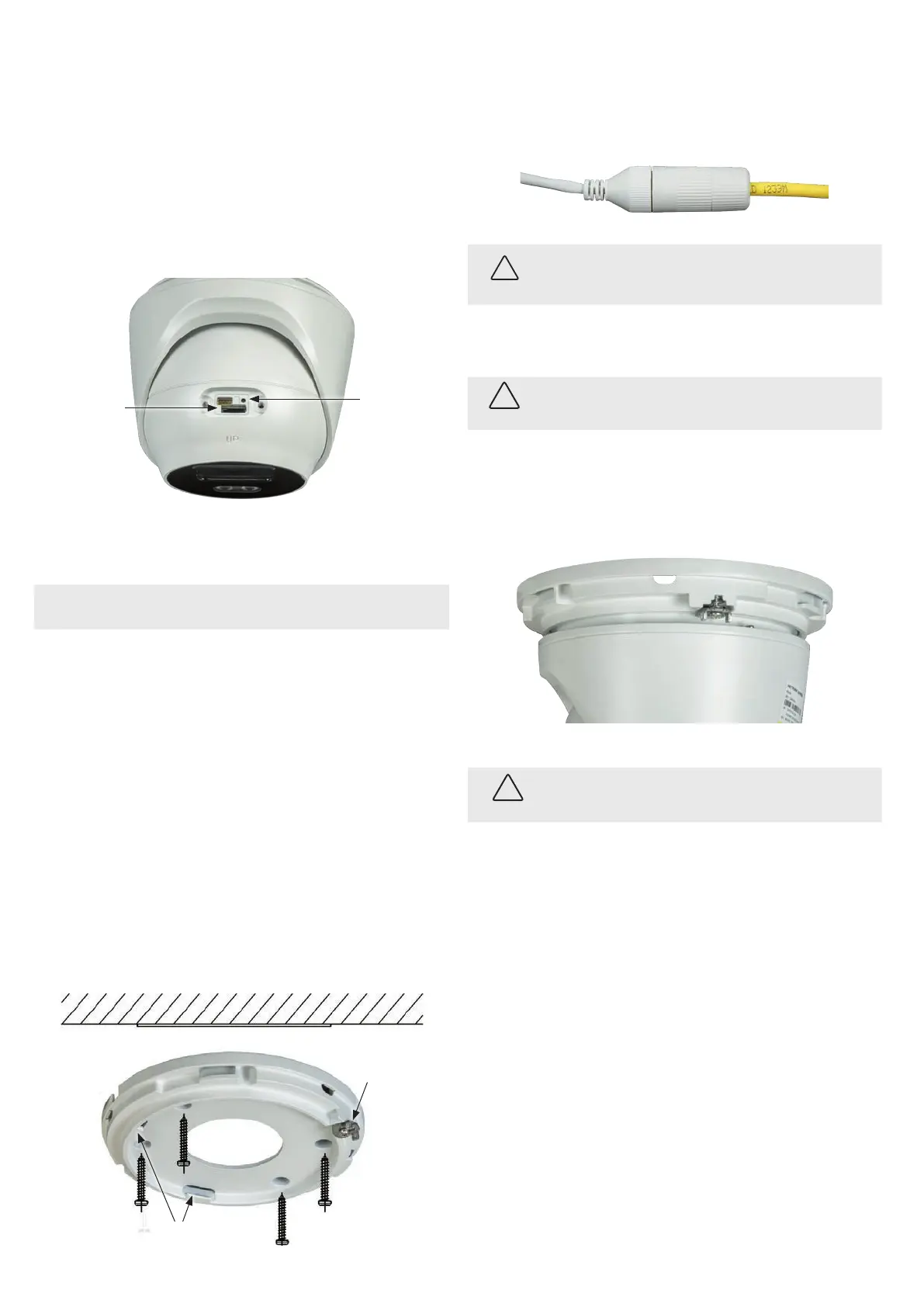
1. Rotate the turret within the shroud and turret assembly to gain access to the maintenance panel
cover.
2. Remove the panel cover using the security L-Wrench provided.
Reset* button
microSD card slot
3. Push the microSD card into the slot until it is fully seated, and then release it. When installed
properly, it will slide into the slot smoothly, and be held in place after release.
4. Reinstall the maintenance panel cover.
NOTE
* RESET: To restore the camera to its default settings, hold down the RESET button for about 10
seconds when the camera is powering on or rebooting. Reset will deactivate the camera and restore
the default IP address, port number, conguration settings, etc.
5. Install the camera
Install the adapter plate
The camera can be mounted onto a wall or ceiling, or onto one of the brackets list above in the
introduction.
The mounting surface should support at least four (4) times the weight of the
camera.
1. To attach the adapter plate using a
ALI-AB1, ALI-AB2, ALI-AA1, ALI-AJ1 or ALI-AA2
bracket:
a. Install the bracket
b. Attach the adapter plate to the bracket using the screws provided.
2. To attach the adapter plate to a mounting surface:
a. Use the drill template or the adapter plate, mark the location of the holes for the mounting
screws. Use the three holes marked “1” for mounting screws to attach the camera to a
surface. If routing the cables into the camera through the mounting surface, mark the
location of the opening in the adapter plate for the cables.
b. Drill holes in the mounting surface where needed for the fasteners and cable routing.
c. Attach the adapter plate to the mounting surface using three screws.
Tabs to hold turret assembly
Fixing screw
and tab
Mounting surface
Connect the interface cables
3. Connect the network LAN and power extension cables to the camera drop cables:
a. Connect the Ethernet LAN cable to the camera LAN drop cable. Protect the connection
from moisture and other contamination, if necessary. A Weatherproof Ethernet Fitting is
provided. Installation instructions for the tting are included later in this document.
Network drop cable
from camera
Network cable from
router or switch
Weatherproof Ethernet Fitting installed
WARNING
!
Failure of the power or Ethernet connector due to moisture or another
contaminant is considered an installation error, which voids the warranty. If
installing this camera in a location such as an overhang, shop, garage, kitchen,
etc. where high humidity or dust is present, seal these connections adequately.
b. If the camera is not powered using PoE (Power over Ethernet injector), connect the 12 Vdc
power cable to the camera drop cable. The polarity of the drop cable connector is shown
in the drop cable photo above.
CAUTION
Do not apply power to the camera at this time. Before applying power to the camera, ensure
that the polarity is correct. An incorrect connection may cause a malfunction and can damage
the camera.
4. For outdoor installations, seal holes drilled in the mounting surface to block moisture and other
contaminants, if necessary.
5. Reattach the camera to the adapter plate. Note that the lip on the turret and shroud assembly is
held in place by the two tabs on the adapter plate (see photo above), and the tab (with the xing
screw) is slid inwards over the lip to secure the camera to the plate. Tighten the xing screw
enough to so the tab doesn’t slip o the lip.
6. Adjust the turret and shroud assembly so that the “UP” mark on the turret is up.
WARNING
!
When applying power to the camera, the LED lamp will switch on for about 5 seconds.
It is very bright.
Avoid looking at the camera when applying power.
7. Apply power to the camera through the 12 Vdc power cable or PoE injector, as congured.
Step 4. Install the Alibi Config Tool software
NOTE: If the camera LAN extension cable is attached to a Network Video Recorder (NVR), skip this step.
The Alibi Cong Tool is a PC-based network utility for discovery of Alibi compatible devices. It provides
an easy way to activate devices, congure camera and recorder network conguration settings, and set
device passwords. It can be installed on a Microsoft® Windows® operating system that has direct access
to the network where your Alibi devices are installed. You can download the Alibi Conguration Tool
from Supercircuits.com or AlibiSecurity.com/Resources.
1. Download the Alibi Cong Tool from the Supercircuits.com or AlibiSecurity.com/Resources
website. At the time when this document was published, the le is named: alibi-cong-tool.
zip and is about 80MB.
2. Un-zip the le on a computer with Microsoft Windows (Windows 7 or newer) that is connected
to the LAN where your Alibi camera is connected.
3. Run the le contained in the zip le: Alibi Cong Tool.exe. Follow the on-screen instructions
to install the le.
4. Open the Alibi Cong Tool application. When the application opens, it automatically “discovers”
and lists all Alibi compatible devices on the LAN. See below.
© 2019 Observint Technologies. All rights reserved.