PLUGGING UP THE CABLES
Where possible use balanced connections to prevent noise and interference pickup especially on long microphone
cable runs. Avoid running audio cables next to AC mains, computer or lighting cables, near thyristor dimmer units
or power supplies etc. The use of low impedance sources such as good quality microphones of 200 ohms or less
significantly reduces interference pickup. Many problems can be avoided by taking time to check that all cables
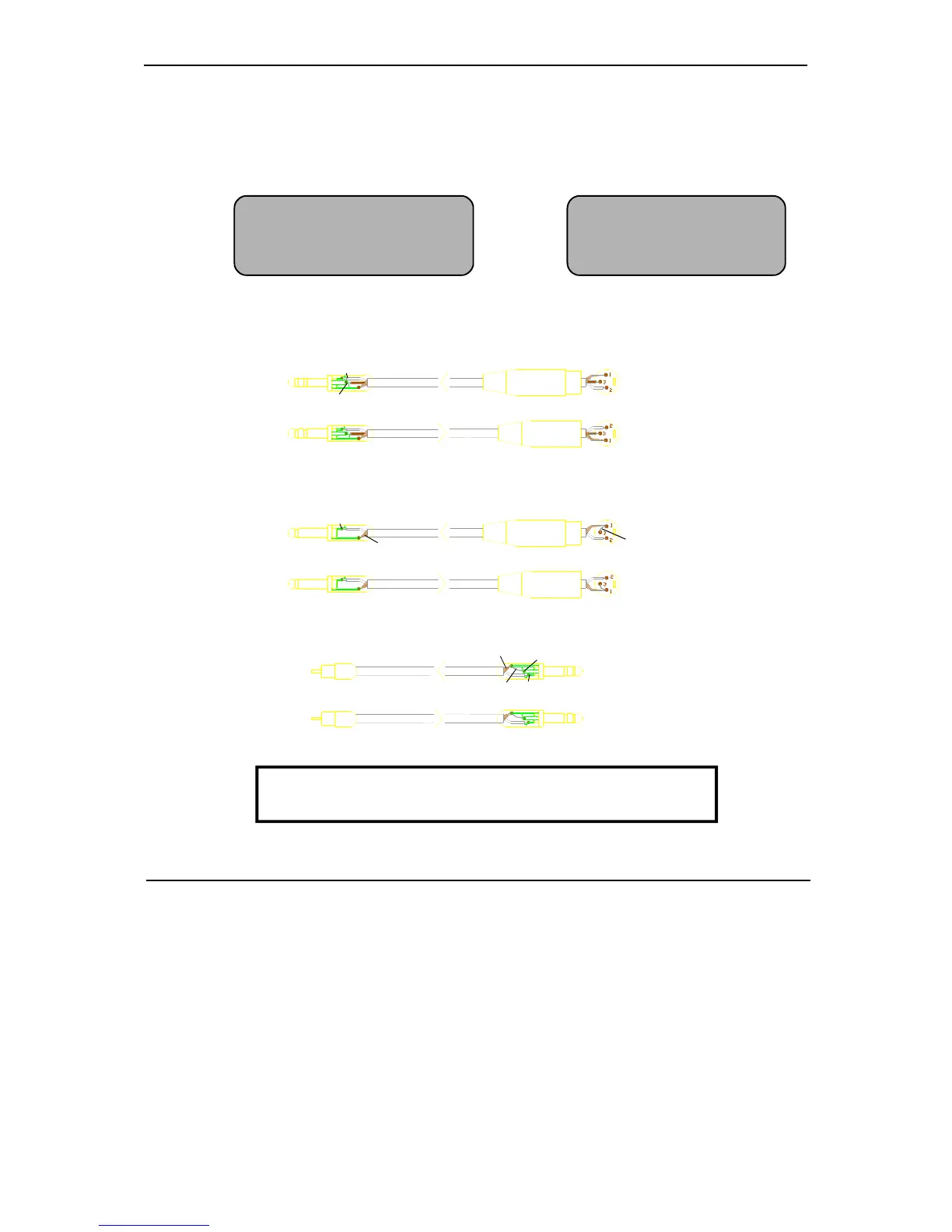
are correctly wired (in-phase) with professional quality cable and carefully soldered connections. The following
wiring convention is used:
ADJUSTING THE LEVELS
For best performance it is important that the connected source signals are matched to the "normal operating level"
of the console. Similarly the console outputs should be correctly matched to the operating levels of the connected
amplifiers and destination equipment. If too high the signal peaks will be clipped resulting in a harsh distorted
sound, and if too low the signal-to-noise ratio is reduced resulting in excessive background hiss.
For best results operate the console with the meters averaging '0' or just below and allowing the loudest passages
and occassional peaks into the 'yellow'. Reduce the gain if the peak indicators flash (red). The GL2000 produces
a standard XLR output level of +4dBu for a meter reading of 0VU. It is advisable to adjust the power amplifier
input gain or fit an attenuator pad if normal console operation results in an output level too high for the connected
amplifier. Normal operation should result in fader levels around the '0' mark.
The GL2000 has an advanced PFL (pre-fade listen) / AFL (after-fader listen) and channel metering system to let
you listen to and check the level of signals at different points in the signal path without affecting the main outputs.
Use the channel PFL switches to set up the input GAIN controls to read an average '0' (yellow LED). Signal activity
is always shown on the channel meters regardless of fader position. The green 'SIG' LED lights at -20dBu to indicate
signal presence, the green '0' LED indicates normal level, and the red 'PEAK' LED warns of potential overload 5dB
before clipping.
Deselect input channel +48V when inputs are connected to
non-phantom powered, mic, line or unbalanced sources.
F
XLR pin 1 = 0V earth shield 1/4" jack tip = + / hot / signal / left / send
pin 2 = + / hot (in phase signal) ring = - / cold / 0V / right / return
pin 3 = - / cold (out of phase signal) sleeve = 0V earth shield
To connect an unbalanced source to a balanced console input, link the cold input (XLR pin 3 or jack ring) to 0V
earth (pin 1 or jack sleeve) at the console. To connect a balanced console output to an unbalanced destination link
the cold output to 0V earth at the console.
BALANCED
UNBALANCED
UNBALANCED
OUTPUT
INPUT
INPUT
3-PIN XLR FEMALE PLUG
3-PIN XLR MALE PLUG
3-PIN XLR FEMALE PLUG
3-PIN XLR MALE PLUG
TWIN SCREENED CABLE
¼" 3-POLE (STEREO) JACK PLUG
Tip
Sleeve
Ring
Tip
Sleeve
Tip
SINGLE SCREENED CABLE
Tip
SINGLE SCREENED CABLE
Sleeve
Ring
Tip
Tip
¼" 3-POLE (STEREO) JACK PLUG
RCA PHONO PLUG
Ring
Sleeve
Ring
Sleeve
OUTPUT
OUTPUT
INPUT
CONSOLE
CONNECTIONS
CONSOLE
CONNECTIONS
CONSOLE
CONNECTIONS
link
link
Screen not connected at destination
¼" 2-POLE (MONO) JACK PLUG
 Loading...