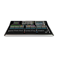
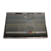
Do you have a question about the ALLEN & HEATH GLD-080 and is the answer not in the manual?
Details warranty conditions for the equipment, including proper installation, operation, and authorized repair.
Refers to a separate document for GLD-080 parts identification, available via Technical Resources.
Repair involves diagnosing faulty PCBs or harnesses; the GLD SBC manages data flow.
Service work should be performed by qualified personnel due to mains power hazards.
Requires a clean, well-lit work surface and appropriate tools for safe servicing.
Emphasizes checking for the latest information from Allen & Heath before starting service.
Instructs to connect to specified mains power types and use an isolation transformer.
Advises using correct power cords and fuses, and not tampering with ground connections.
Details steps before opening, including switching off power and ensuring safety shields are in place.
Covers post-service checks, cleaning, alignment, and configuration to prevent future failures.
Read safety instructions and test service work for successful completion before operating.
Use adequate packaging and handle the unit with care when lifting or moving.
Ensure correct console connection and mains voltage setting for local supply.
Trace signal flow via circuit path and block diagram for effective diagnosis.
States that Allen & Heath does not publish schematics for digital audio and control circuitry.
Refers to a separately published document for parts identification for distributors.
Identifies the 8 channel LCD module AE8429.
Identifies the 8 channel board, part number 004-177.
Identifies the 12 channel board, part number 004-176.
Identifies the 12 channel LCD module AE8430.
Identifies the Bank Right 2 module, part number 004-182.
Identifies the fader slave module, part number 004-179.
Identifies the Bank Mid 1 module, part number 004-181.
Identifies the fader master module, part number 004-178.
Instruction to remove the screws located on the rear of the unit.
Instruction to remove the screws located on the lower section of the unit.
Procedure to lift the rear section of the unit to access internal components.
Instruction to disconnect a specific cable during the disassembly process.
Identifies the Processor board, part number 004-276.
Identifies the System Base Controller board, part number 004-191.
Identifies the DSP mini backplane, part number 004-288.
Identifies the Fan Controller board, part number 004-186.
Identifies the Power Supply Unit, part number 004-282.
Identifies the Audio/Power interface board, part number 004-184.
Identifies the DSP board, part number 004-173.
Use a heat source to warm the screen overlay before removal.
Press the center of the screen to detach it from the adhesive.
Support the screen from the rear as it detaches from the adhesive.
Complete the removal of the screen from the unit.
Details components located in the rear base section of the system.
Details components located on the top surface of the system.
Illustrates the DC power wiring connections and color codes.
Lists the color codes for ATX wire connections.
Details the main AC to DC Power Supply Unit (PSU).
Shows connections for the Audio Top Board.
Details connections for the Local Audio & Power Interface Board.
Details connections for the IGL DSP Mini Backplane.
Details connections for the IGL DSP Board.
Details connections for the Fan Controller Board.
Details connections for the System Base Controller (SBC) Board.
Details connections for the Processing & M3 Board.
Details connections for the Processing LED Board.
Details connections for the Touch Screen module.
Details connections for the IGL TFT Right module.
Details connections for the Headphone Board module.
Details connections for the 12 Channel LCD Module.
Details connections for the 12 Channel Board.
Details connections for the Bank M module.
Details connections for the 8 Channel LCD Module.
Details connections for the 8 Channel Board.
Details connections for the Bank R module.
Details connections for the M3 12 Fader Master module.
Details connections for the 8 Fader Slave module.
Shows connections for the IGL DSP Board.
Shows connections for the Processing & M3 Board.
Shows connections for the Local Audio & Power Interface Board.
| Type | Digital Mixer |
|---|---|
| Channels | 48 |
| Inputs - Line | 8 |
| Outputs - Main | 2 |
| Sampling Rate | 48 kHz |
| Effects | Reverb, Delay, Modulation |
| I/O Expansion Slots | 2 |
| Display | Touchscreen |
| Fader Throw | 100 mm |
| Word Clock | Yes |
| Power Supply | Internal |
| EQ Bands | 4-band parametric |
| Dynamic Processing | Compressor, Gate |
| Computer Connectivity | USB |
| Connectivity | Ethernet |
| Dante Option | Yes |
| Inputs - Mic Preamps | 8 |
