Do you have a question about the ALLEN & HEATH ZED 14 and is the answer not in the manual?
Retain safety and operating instructions for future reference and adhere to all warnings printed here and on the console.
Operate the console with its covers correctly fitted to prevent risk of electric shock.
Connect the console only to the specified mains power unit type marked on the rear panel.
Route the power cord to prevent it from being walked on, stretched, or pinched by items.
Do not defeat the grounding means of the power cord plug; this equipment must be earthed.
Do not expose the console to rain or moisture or use in damp or wet conditions.
Do not obstruct ventilation slots to ensure adequate airflow required for console ventilation.
Locate the console away from excessive heat, direct sunlight, or heat-producing equipment.
Refer servicing to qualified technical personnel if the equipment is exposed to moisture or damage.
Install the console according to the user guide, do not connect amplifier outputs directly.
Instructions for replacing the mains plug, including wire colour coding for European and USA/Canada.
Precautions for damage prevention, environment, cleaning, transporting, and hearing safety for the console.
Details on the two-stage pre-amp design for high gain and low noise, with mic and line input considerations.
Explanation of the 3-band EQ on mono channels and 2-band EQ on stereo channels for sound shaping.
Information on the four auxiliary buses (2 pre-fade, 2 post-fade) for monitoring or effects sends.
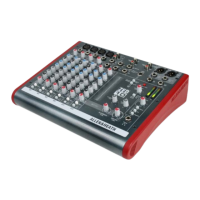
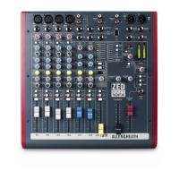
Overview of six mono and four stereo channels offering flexible input options including USB audio.
Explanation of the flexible and easy USB audio connection for transferring audio to and from a computer.
Details on the standard 3-pin XLR socket wiring and connection for microphone input.
Description of the 1/4" jack socket for line level signals, which overrides the mic input.
Information on the 1/4" jack socket for unbalanced insert send/return signals.
Explains how the gain control adjusts input amplifier signal level for mic and line inputs.
Describes the 2-pole filter for reducing pop noise and rumble from microphone signals.
Details the High Frequency equalizer affecting higher audible frequencies with a 12kHz corner frequency.
Explains the Mid Frequency equalizer covering the middle audible range with sweepable frequencies.
Describes the Low Frequency equalizer affecting the low end of the audio range with an 80Hz corner frequency.
Controls for sending signals to auxiliary buses 1 & 2, sourced pre-fade for monitoring or recording.
Controls for sending signals to auxiliary buses 3 & 4, sourced post-fade for effects sends.
Control for adjusting signal distribution between left and right stereo buses.
Function to mute the signal to the main LR and auxiliary buses, indicated by an LED.
Pre-Fade Listen switch for monitoring channel signals and PK! LED indicating signal level and clipping.
100mm fader controlling channel signal level to main LR buses and Auxes 3 & 4.
Additional stereo input via phono connectors for ST RTN, can be routed to stereo channel or main bus.
Adjusts the level of the stereo return input, with a gain range of 0 to 10dB.
Switch to turn the stereo return signal on or off, recommended to leave off when not in use.
Selects whether the Stereo Return signal is sent to the L R bus or stereo channel I.
Standard 1/4" jack sockets for line level stereo signals, usable with mono inputs.
Adjusts the level of the ST1 input, with a range from off to +10dB.
2-band equalizer for stereo channels with corner frequencies at 12kHz (HF) and 80Hz (LF).
Switch to configure Auxes 1 & 2 as mono sends or a stereo send pair for monitoring or recording.
Controls for signal level to Aux 1 & 2 buses, pre-fade, muted with mute switch.
Controls for signal level to Aux 3 & 4 buses, post-fade, muted with mute switch, used for effects.
Control for adjusting relative levels between the left and right stereo channels.
Mutes signals to the main L R and auxiliary buses, indicated by an LED.
Pre-Fade Listen switch for monitoring stereo channel signals and PK! LED indicating signal level.
100mm fader controlling channel signal level to main L R buses and Auxes 3 & 4.
Details Stereo Input Channel 9-10, noting difference in additional stereo input labelling (2 Track Return).
Describes Stereo Input Channel 11-12 with USB audio input and analogue record output via phono sockets.
Explains Stereo Input Channel 13-14 with one stereo input and alternate stereo output via master section controls.
Information on the USB type B connector and selector switches determining signal sent on USB output.
Description of 1/4" jack sockets for Aux 1 to 4 outputs, with impedance balanced nominal level.
Details 1/4" jack sockets for unbalanced insert send/return signals for the main mix.
Explanation of XLR sockets for main left & right outputs, impedance balanced signals.
Description of the mono sum of the main left & right post-fade signals output.
Details 1/4" and 3.5mm sockets for stereo headphones, recommending higher impedance.
Switch to provide 48v Phantom Power to Mic input XLRs; instructions on safe usage provided.
12 segment LED meters displaying signal levels from monitor selectors or PFL signals, with '0' reflecting OdBu.
Switches to select signal source for headphones monitor and meters, with priority system explained.
Control for adjusting the headphone signal level and a warning about high volume.
Level control for the Alt (Alternate) Output, used for connecting separate monitor speakers.
Switches to select signal source for the Alt output, choosing between pre-fade, post-fade, or monitor signals.
Controls for adjusting the level of the Aux 1 and 2 outputs, with a range from off to +6dB.
100mm faders for main L R outputs, providing 10dB gain at top and unity gain at '0'.
Highlights of SONAR LE, including track counts, audio quality, effects, and compatibility with Windows operating systems.
Technical prerequisites for installing and running SONAR LE software on a computer system.
Instructions for installing the SONAR LE software by inserting the CD/DVD ROM drive and following on-screen prompts.
Steps to configure SONAR LE software to communicate audio with the ZED mixing console via USB connection.
| Type | Analog |
|---|---|
| Channels | 14 |
| Mic Inputs | 6 |
| Line Inputs | 8 |
| USB Audio Interface | Yes |
| Phantom Power | Yes |
| Inputs - Mic Preamps | 6 |
| Outputs - Main | XLR |
| USB | 1 x USB Type B |
| Headphone Output | 1/4" TRS |
| EQ Bands | 3-band with swept mid |