Malfunctions Not Indicated by a Fault 3-23
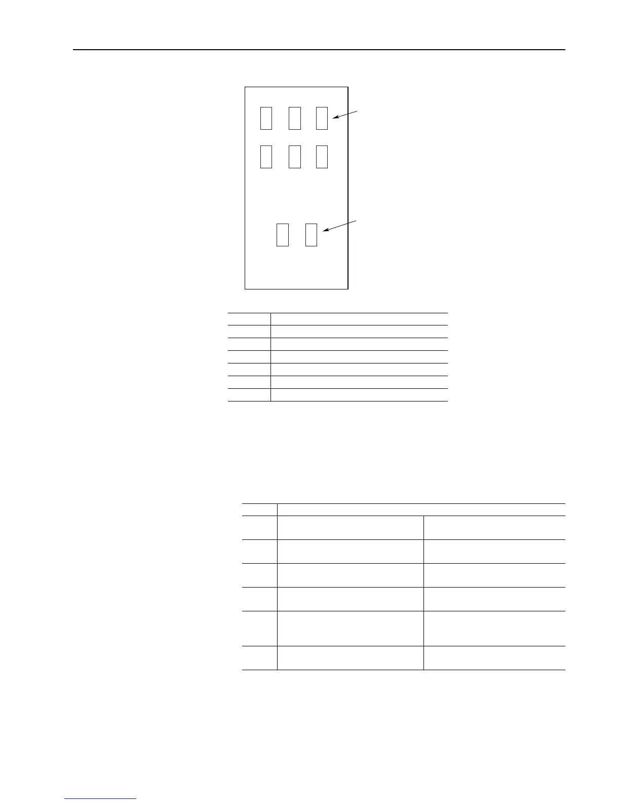
Figure 3.13 Series A SCR Layout
All resistances should be 100k ohms or greater. If a low resistance is
detected replace the affected SCR pack.
3. Check the gate to cathode junction of each SCR module. With the DVM
on the 1K ohm scale, measure resistance of each junction as follows:
(lead orientation is not critical)
All resistances should be between 7 to 30 ohms. If a measurement is
outside of this range or if one reading deviates significantly from the
majority, then module replacement may be necessary.
Module Measurement Point
PM1 A1 (Bottom of DC contactor) to L1 (bottom of F1)
PM2 A1 (bottom of DC contactor) to L2 (bottom of F2)
PM3 A1 (bottom of DC contactor) to L3 (bottom of F3)
PM4 A2 (bottom of DC contactor) to L1 (bottom of F1)
PM5 A2 (bottom of DC contactor) to L2 (bottom of F2)
PM6 A2 (bottom of DC contactor) to L3 (bottom of F3)
Module Measurement Points
PM1 G1 (Top of left arm/snubber board) to A1
(See above)
G2 (Top of left arm/snubber board)
to L1 (See above)
PM2 G1 (Top of middle arm/snubber board)
to A1 (See above)
G2 (Top of middle arm/snubber board)
to L2 (See above)
PM3 G1 (Top of right arm/snubber board)
to A1 (See above)
G2 (Top of right arm/snubber board)
to L3 (See above)
PM4 G1 (Bottom of left arm/snubber board)
to A2 (See above)
G2 (Bottom of left arm/snubber board)
to L1 (See above)
PM5 G1 (Bottom of middle arm/snubber
board)
to A2 (See above)
G2 (Bottom of middle arm/snubber
board)
to L2 (See above)
PM6 G1 (Bottom of right arm/snubber board)
to A2 (See above)
G2 (Bottom of right arm/snubber board)
to L3 (See above)
PM1 PM2 PM3
PM4 PM5 PM6
PM8 PM7
Armature SCR Module
Field SCR Module
Aotewell Ltd industry-mall.net

 Loading...


