3-24 Malfunctions Not Indicated by a Fault
Armature Pulse/Snubber Boards (Series A)
The Armature Pulse/Snubber Boards provide isolation of the gate pulse
firing circuit and also provide DV/DT protection for the SCR modules. A
malfunction of these devices will be evident in either an overcurrent related
fault, blown or tripped incoming protection devices, or erratic motor
operation. Follow the procedure below if a board malfunction is suspected.
1. Disconnect and lock-out ALL incoming voltage sources.(See above)
2. Remove all three Pulse Boards by disconnecting the ribbon cable at J1.
Remove the upper and lower gate leads at G1 and G2. Loosen the captive
thumb screws designated DCA1, AC, and DCA2. Measure the following
resistances with the DVM on the 200 ohms scale. (lead orientation is not
critical)
3. If any of these measurements (G1 through J6) are out of tolerance,
replace the associated board. If these procedures check out and no
apparent discrepancies are found, a potential problem could still exist. If
a “breakdown path” has been established from the pulse transformer
primary to secondary, it is possible that a malfunction could show itself
when the line voltage potential is applied to the power structure. This
condition can only be detected by “hi potting” the board at a level of
2500Vrms, and verifying less than 5mA from primary to secondary.
Field SCR’s (Series A)
The 1395 field supply consists of two dual pack SCR modules arranged in a
single–phase full wave rectifier configuration. Malfunction of any of these
components may cause various responses including field and velocity
related faults, or blown fuses at F4 and F6. The following procedures can be
used if field bridge malfunctions are suspected.
1. Disconnect and lock–out ALL incoming voltage sources. Verify that the
3 phase high voltage is removed from the incoming protection devices,
either F1 – F3 or the main circuit breaker CB1. Also verify that the 115V
logic supply and contactor power is removed from TB2–3, 4, and 5. If an
external field supply is used, verify that it is likewise removed by
checking TB1–1 and 5.
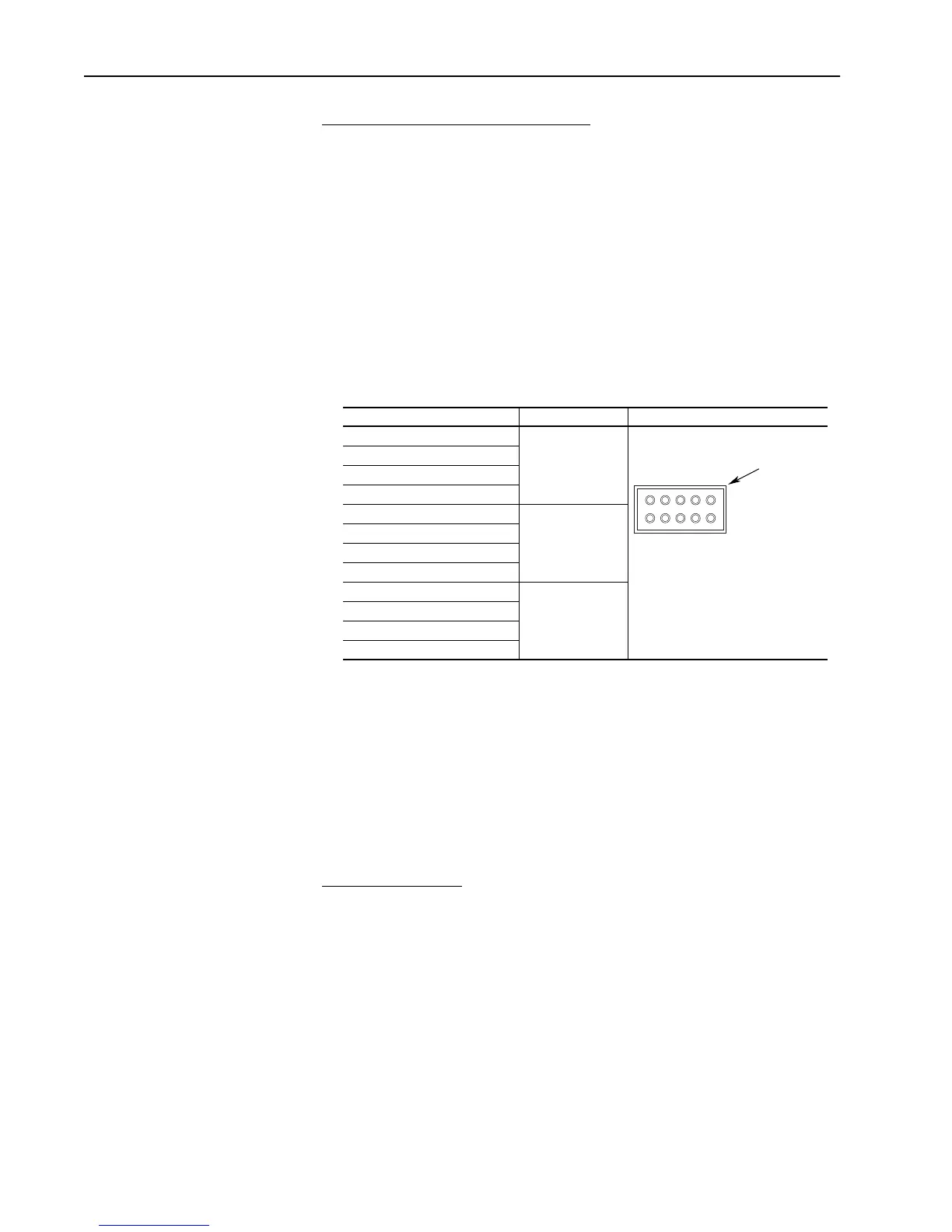
Measurement Point Measurement J1 Pin Orientation
G1 (upper) to DCA1 100 ohms 10%
G1 (lower) to DCA2
G2 (upper) to AC (2L1)
G2 (lower) to AC (3L1)
D1 (anode) to DCA1 1 to 2 ohms
D2 (anode) to AC (2L1)
D3 (anode) to AC (3L1)
D4 (anode) to DCA2
J1-1 to J1-8 100 ohms 10%
J1-2 to J1-8
J1-3 to J1-8
J1-6 to J1-8
97 531
10 8 6 4 2
Arrow on header
Aotewell Ltd industry-mall.net

 Loading...


