3
4
2
(2)
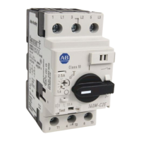
Settaggio di default manuale
Manual default setting
Manuelle Default-Einstellung
Configuration par défauit manuelle
Ajuste de default manual
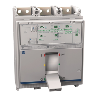
In = 40A
I1 = 15A
t1 = 12s @45A (3I1)
Example - Esempio - Beispiel - Exemple - Ejemplo
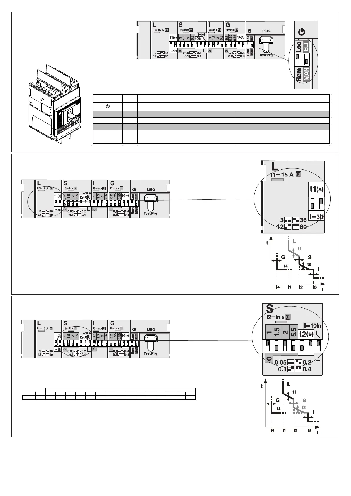
In = 40A
I2 = 40x(1+2)=120A
2
t2 (I t=ON) = 0,1s @400A (10In)
Example - Esempio - Beispiel - Exemple - Ejemplo
In (A) 1 1,5 2 2,5 3 3,5 4,5 5,5 6,5 7 7,5 8 8,5 9 10
140 G-J 40 40 60 80 10 0 120 14 0 18 0 22 0 26 0 28 0 30 0 32 0 34 0 36 0 40 0
I2 (In)
Green
L Red LED Fixed = L pre alarm (0,9 * I1 < I < 1,2 * I1) LED Blinking = L alarm (I > 1,2 * I1)
S Red
G Red
L | S | I | G Red
LED Fixed = Device active
LED Blinking = G alarm (I > I4)
LED Blinking = Parameters inconsistency - S >= I.
LED Blinking without Parameters inconsistency = generic fault (please contact Rockwell Automation)
LED Color CONDITION Run time
LED Blinking = S alarm (I > I2)
DIR 1000721R0510 Version 00

 Loading...