6
7
5
(3)
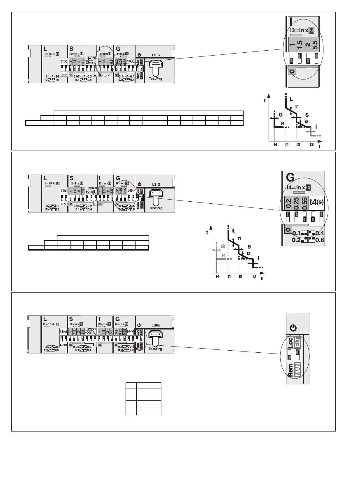
Settaggio di default elettronico
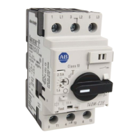
In = 40A
I3 = 40x(1,5+5,5)=280A
Example - Esempio - Beispiel - Exemple - Ejemplo
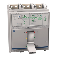
In = 40A
I4 = 40x(0,2+0,25)=18A
t4 = 0,2s @ I>I4
Example - Esempio - Beispiel - Exemple - Ejemplo
Electronic default setting
elektronische Default Einstellung
Configuration par défaut
électronique
Ajuste de default electrónico
L 15A
t1 60 s
S Off
I 4,5 x In
G Off
In (A ) 1 1,5 2 2,5 3 3,5 4,5 5,5 6,5 7 7,5 8 8,5 9 10
140G-J 40 40 6 0 80 10 0 120 14 0 180 220 260 280 300 32 0 340 360 400
I3 (In)
In (A ) 0,2 0,25 0 ,4 5 0,55 0 ,75 0 ,8 1
14 0 G-J 40 8 10 18 22 30 32 40
I4 (In)
DIR 1000721R0510 Version 00

 Loading...