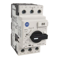
Fig.
2-
IO.
Cover Screw
lnstalla
tion Positions
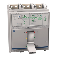
Modification
r
Label
Terminal Black
I
Terminal Block
Connection
Diaaram
Label
(When Used)
Pigtail Lead
Connection
Diagram
Label
(When Used)
Fig.
2-
I I. Preferred Mounting Locations for Accessory
Nameplate Labels
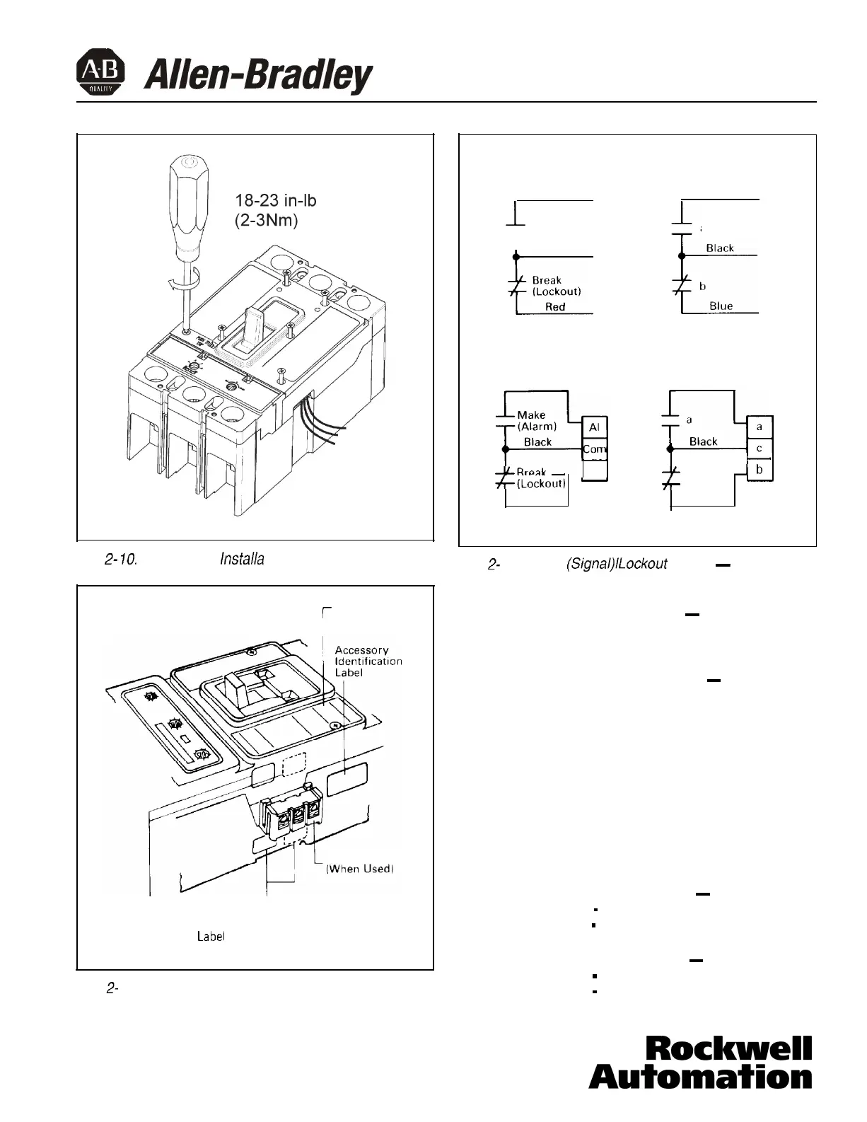
Pigtail Leads
ASL Switch
Blue
Auxiliary Switch
Red
1
Make
T
(Alarm)
Leads Are Bundled and
Tagged “B”
Terminal Block
Blue
--CBreak
-
Lo
+(Lockout)
-
Red
ASL Switch
a
Leads Are Bundled and
Tagged “A”
Red
-
+t
b
-b
-
Blue
Auxiliary Switch
Fig.
2-
12. Alarm
(Signat)lLockout
Switch
-
Auxiliary
Switch Connection Diagram
b.
Circuit breaker handle ON
-
Check that make
contact(s) are open and break contact(s) are
closed.
C.
Press PUSH-TO-TRIP button
-
Check that
make contact(s) are closed and break con-
tact(s) are open.
d.
If ASL switch fails test, make sure that module
is properly seated in trip unit slots. If problem
persists. contact Allen-Bradley.
2-17. Test auxiliary switch (when supplied). Connect con-
tinuity tester or ohmmeter across pigtail leads or
terminal block connections. Check continuity as fol-
lows:
a.
Circuit breaker handle OFF
-
“a” contact
-
open
“b” contact
-
closed.
b.
Circuit breaker handle ON
-
“a” contact
-
closed
“b” contact
-
open.
40752-035(1) Effective 3/02
Page 7
 Loading...