EasyManuals Logo

Allen-Bradley 1746 Series User Manual

Allen-Bradley 1746 Series
56 pages
To Next Page IconTo Next Page
To Previous Page IconTo Previous Page
Page #31 background imageLoading...
Page #31 background image
Discrete I/O Modules 31
Publication 1746-IN005A-US-P
Removable Terminal Blocks
Colored terminal blocks are removable by loosening the upper and lower
retaining screws. Black terminal blocks are not removable.
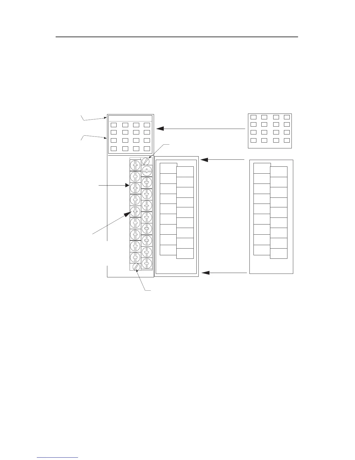
Figure 1:Installing Octal Labels
Beveled Edge
Removable
Terminal
Block
Terminal Wiring
max. #14 AWG (2mm
2
)
max. 2 wires per terminal
max. torque: 0.9Nm (8 in-lbs)
Upper Retaining Screw Maximum
Torque = 0.6 Nm (5.3 in-lbs)
Module Color Bar
Lower Retaining Screw Maximum
Torque = 0.6 Nm (5.3 in-lbs)
Octal Door Label
1746-XXXX 1746-XXXX(OCTAL)
Octal Filter Label
OCTAL
Allen-Bradley Spares

Questions and Answers:

Question and Answer IconNeed help?

Do you have a question about the Allen-Bradley 1746 Series and is the answer not in the manual?

Allen-Bradley 1746 Series Specifications

General IconGeneral
CategoryI/O Systems
Shock Resistance30G
Backplane CurrentVaries by module. Refer to individual module specifications.
Operating Temperature0°C to 60°C (32°F to 140°F)
Storage Temperature-40°C to 85°C (-40°F to 185°F)
Relative Humidity5% to 95% (non-condensing)
Voltage RangeVaries by module. Refer to individual module specifications.
SeriesAllen-Bradley 1746
Module TypeDigital/Analog I/O Modules

Related product manuals