EasyManuals Logo

Allen-Bradley 1746 Series User Manual

Allen-Bradley 1746 Series
56 pages
To Next Page IconTo Next Page
To Previous Page IconTo Previous Page
Page #6 background imageLoading...
Page #6 background image
6 Discrete I/O Modules
Publication 1746-IN005A-US-P
Installation
!
ATTENTION: Never install, remove, or wire modules with
power applied to chassis.
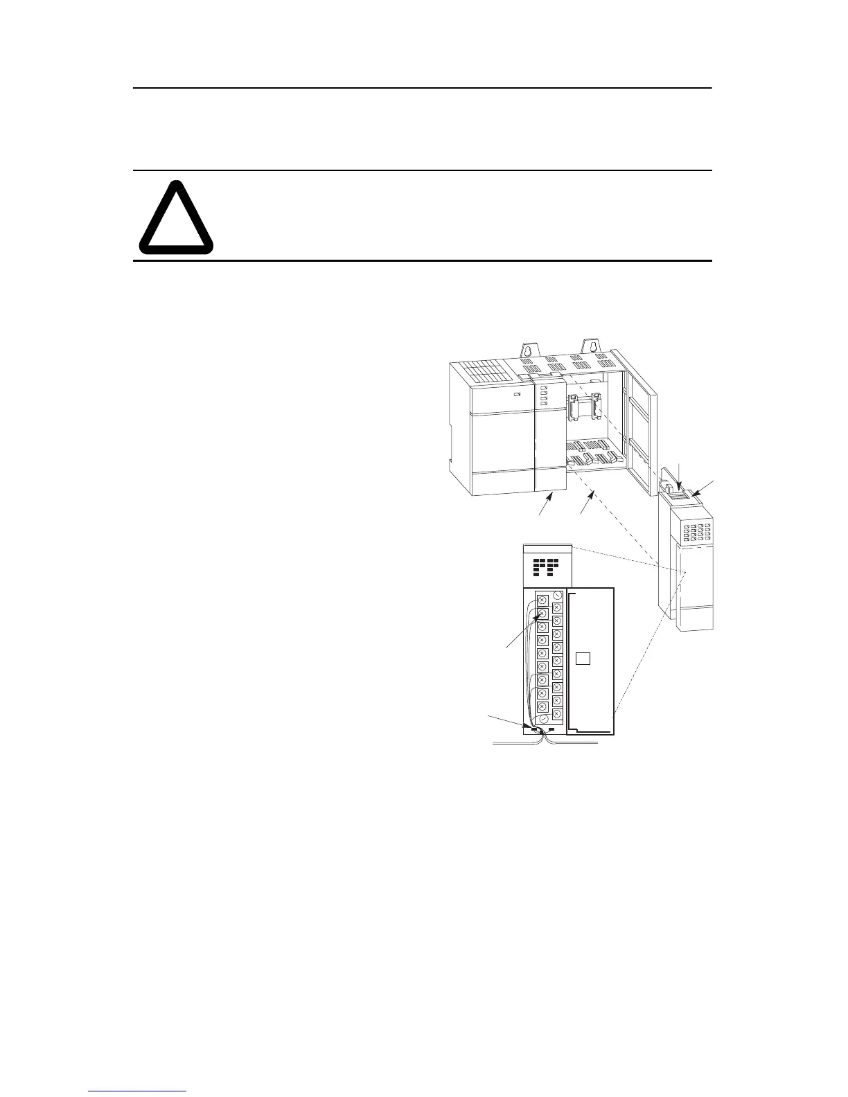
IMPORTANT: The first slot of the chassis is reserved for the processor or the
1747-ASB module.
Slot 1
A
B
D
C
max. #14 AWG (2 mm
2
)
max. 2 wires per terminal
max. torque: 0.9 Nm (8
in-lbs)
1. D
i
sconnect power.
2. Align circuit board of
module with chassis card
guide. (A)
3. Slide the module into the
chassis until the bottom tabs
lock into place. (B)
4. Route the wires down and
away from the module,
securing them with the wire
tie. (C)
5. To keep the chassis free
from debris, cover all
unused slots with Card Slot
Filler, catalog number 1746-
N2.
To remove the module,
press and hold the module
release located on each self-
locking tab, and slide the
module out of the chassis
slot. (D)

Questions and Answers:

Question and Answer IconNeed help?

Do you have a question about the Allen-Bradley 1746 Series and is the answer not in the manual?

Allen-Bradley 1746 Series Specifications

General IconGeneral
CategoryI/O Systems
Shock Resistance30G
Backplane CurrentVaries by module. Refer to individual module specifications.
Operating Temperature0°C to 60°C (32°F to 140°F)
Storage Temperature-40°C to 85°C (-40°F to 185°F)
Relative Humidity5% to 95% (non-condensing)
Voltage RangeVaries by module. Refer to individual module specifications.
SeriesAllen-Bradley 1746
Module TypeDigital/Analog I/O Modules

Related product manuals