14 Rockwell Automation Publication CNET-IN005A-EN-P - May 2011
Chapter 1 Install a 1756 ControlNet Communication Module
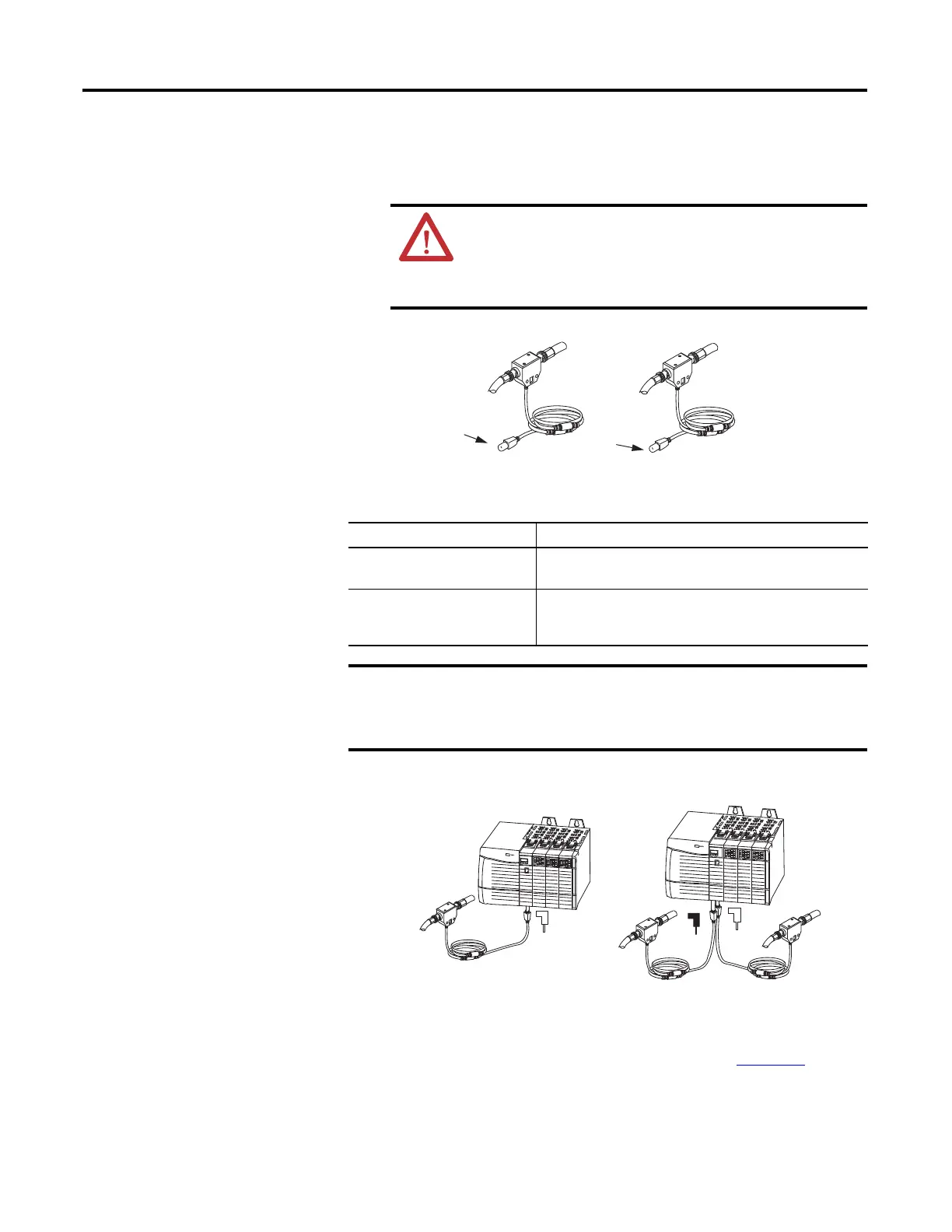
To connect the module to the network with a tap, perform this procedure.
1. Remove and save the dust caps from the ControlNet taps.
2. Connect the tap’s straight or right-angle connector to the module’s BNC
connector.
3. Apply power to the module and check the status indicators to determine
whether the power supply and module are operating properly.
For more information about status indicators, refer to Chapter A
.
ATTENTION: Do not allow any metal portions of the tap to
contact any conductive material. If you disconnect the tap from the
module, place the dust cap back on the straight or right-angle
connector to prevent the connector from accidentally contacting a
metallic grounded surface.
If your network supports Then connect the tap’s connector
Nonredundant media
(all 1756-CNx modules)
From trunkline A to channel A on the module.
Redundant media
(1756-CNBR/E, 1756-CN2R/B, and
1756-CN2RXT modules)
From trunkline A to channel A on the 1756-CN2R/B module.
From trunkline B to channel B on the 1756-CN2R/B module.
To avoid accidentally reversing the tap connections, before making your
connection, check the tap drop cable for the label indicating the attached
segment. Accidental connection reversals produce incorrect status
displays and require troubleshooting.
Trunkline A
Trunkline B
1756-CN2/B Trunkline A
1756-CN2R/B Trunklines A and B
Dust Cap
Dust Cap
Network 1
Network 2
A
A
B
Tap
Tap
Tap
Nonredundant Media
Redundant Media

 Loading...
