6 Compact I/O High-speed Counter Module
Publication 1769-IN030B-EN-P - October 2010
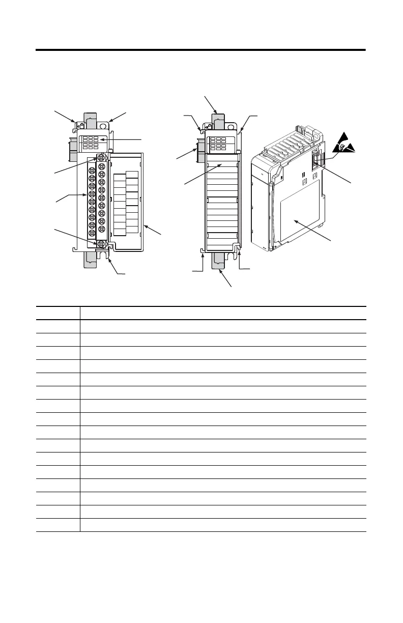
Hardware Description
Item Description
1Bus lever
2a Upper-panel mounting tab
2b Lower-panel mounting tab
3 Module status indicators (6 Input, 4 Output, 1 Fuse, 1 OK)
4 Module door with terminal identification label
5 Removable terminal block (RTB) with finger-safe cover
5a RTB upper-retaining screw
5b RTB lower-retaining screw
6a Movable bus connector (bus interface) with female pins
6b Stationary bus connector (bus interface) with male pins
7 Nameplate label
8a Upper tongue-and-groove slots
8b Lower tongue-and-groove slots
9a Upper DIN-rail latch
9b Lower DIN-rail latch
10 Write-on label for user identification tags
1769-HSC
DANGER
Do Not Remove RTB Under Power
Unless Area is Non-Hazardous
Ensure Adjacent
Bus Lever is Unlatched/Latched
Before/After
Removing/Inserting Module
OUT 2
A1-
Z1-
OUT DC
COM
B0-
Z0-
B1-
OUT 0
OUT DC
+5V/24V
A0+
Z0+
B1+
OUT 3
OUT 1
B0+
A1+
Z1+
A0-
High Speed Counter
02
13
A0 B0
A1 B1
Z0
Z1
IN OUT
High Speed Counter
02
13
A0 B0
A1 B1
Z0
Z1
IN OUT
1
2a
3
4
2b
5b
5
5a
10
6a
8a
9a
8a
6b
7
8b
8b
9b
45196

 Loading...


