10 Compact I/O High-speed Counter Module
Publication 1769-IN030B-EN-P - October 2010
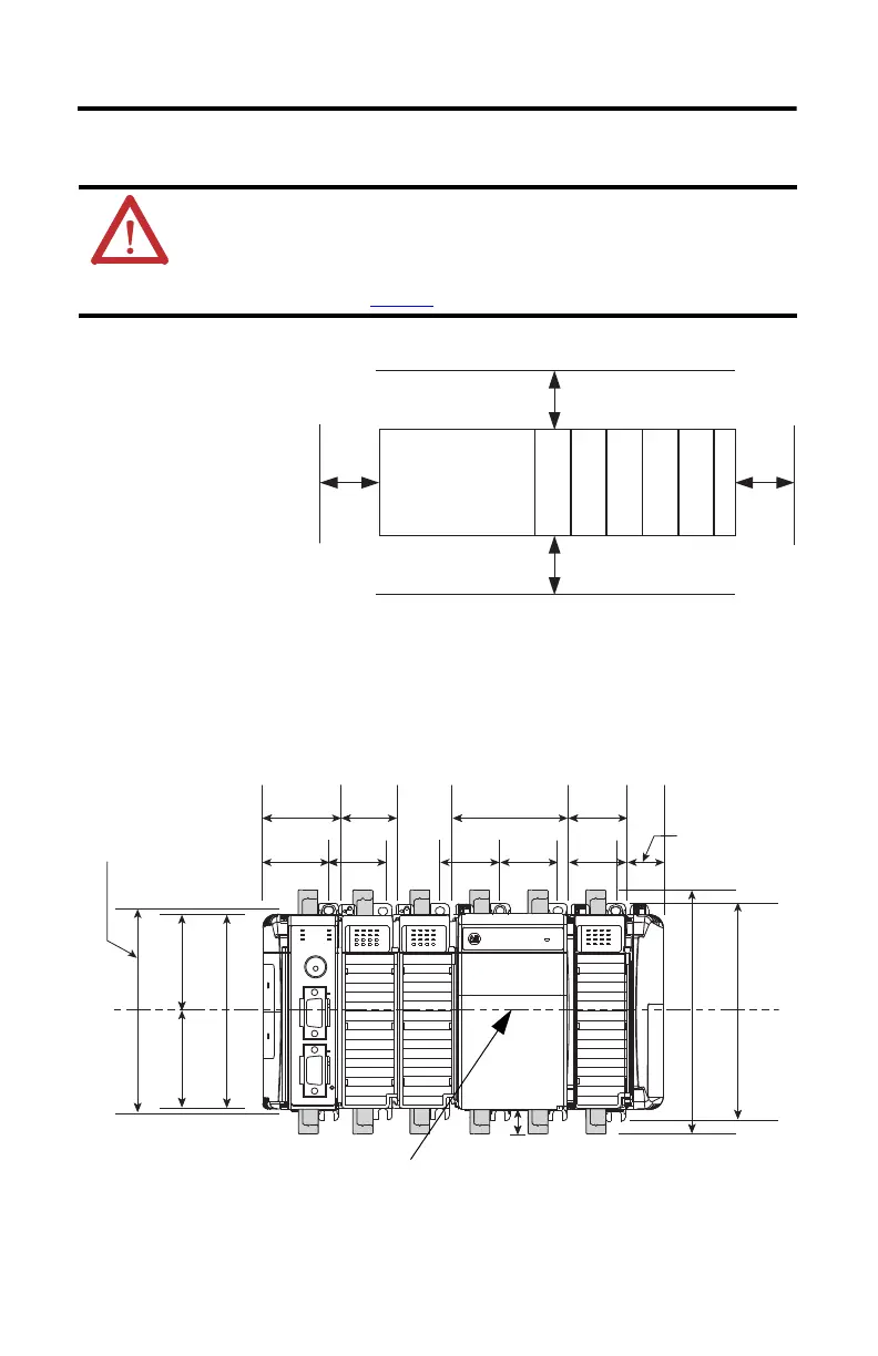
System Mounting
Minimum Spacing
Maintain spacing from
enclosure walls, wireways,
adjacent equipment, and so
forth. Allow 50 mm (2 in.) of
space on all sides for adequate
ventilation, as shown in the
illustration.
Panel Mounting
Mount the module to a panel by using two screws per module. Use M4 or #8 panhead screws.
Mounting screws are required on every module.
Figure 1 - Compact I/O Modules with CompactLogix Controller
and Power Supply
ATTENTION: This product is intended to be mounted to a well-grounded mounting
surface, such as a metal panel. Additional grounding connections from the power
supply's mounting tabs or DIN rail (if used) are not required unless the mounting
surface cannot be grounded. Refer to Industrial Automation Wiring and Grounding
Guidelines, publication 1770-4.1
, for additional information.
Top
Side
Bottom
Side
Controller
Compact I/O
Compact I/O
Compact I/O
Compact I/O
Compact I/O
End Cap or Cable
45198
Important: Hole spacing tolerance: ±0.04 mm (0.016 in.).
Mounting Hole
Dimension
122.6 mm (4.83 in.)
59 mm
59 mm
118 mm (4.65 in.)
(2.32 in.) (2.32 in.)
132 mm (5.19 in.)
147.4 mm (5.81 in.)
14.7 mm
(0.58 in.)
DIN Rail Center Line
50 mm 35 mm
35 mm 35 mm 35 mm 35 mm
35 mm70 mm
(1.97 in.)
(1.38 in.)
(2.76 in.)
(1.38 in.)
40 mm
28.5 mm
(1.12 in.)
(1.58 in.) (1.38 in.) (1.38 in.)(1.38 in.) (1.38 in.)

 Loading...


