Compact I/O High-speed Counter Module 11
Publication 1769-IN030B-EN-P - October 2010
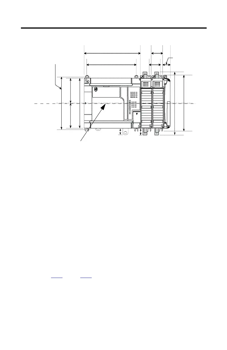
Figure 2 - Compact I/O Modules with MicroLogix 1500 Base Unit and Processor
Panel Mounting Procedure by Using Modules as a Template
This procedure lets you to use the assembled modules as a template for drilling holes in the panel.
Due to module mounting hole tolerance, it is important to do these steps.
1. On a clean work surface, assemble no more than three modules.
2. Using the assembled modules as a template, carefully mark the center of all
module-mounting holes on the panel.
3. Return the assembled modules to the clean work surface, including any previously
mounted modules.
4. Drill and tap the mounting holes for the recommended M4 or #8 screw.
5. Place the modules back on the panel, and check for proper hole alignment.
6. Attach the modules to the panel using the mounting screws.
7. Repeat step 1
through step 6 for any remaining modules.
45199
Important: Hole spacing tolerance: ±0.04 mm (0.016 in.).
168 mm
(6.62 in.)
147 mm
(5.79 in.)
Mounting Hole
Dimension
35 mm
35 mm
(1.38 in.)
(1.38 in.)
122.6 mm (4.83 in.)
59 mm59 mm
(2.32 in.) (2.32 in.)
147.4 mm (5.81 in.)
132 mm (5.19 in.)
28.5 mm
(1.12 in.)
DIN Rail Center Line
13.5 mm
(0.53 in.)
14.7 mm
(0.58 in.)
118 mm (4.65 in)

 Loading...


