28 Rockwell Automation Publication 1769-UM021G-EN-P - October 2015
Chapter 1 Install the CompactLogix 5370 L1 Controller
• Not all Class 2/SELV-listed power supplies are certified for use in all
applications, for example, use in nonhazardous and hazardous
environments.
Before installing an external power supply, consult all specification and
certification information to verify that you are using an acceptable external
power supply.
• Only for example purposes, this section describes how to use a 1606-
XLE120E, NEC Class 2 switched-mode power supply. The exact steps for
other external power supplies can vary from the steps that are described
here.
Complete these steps to connect power to the CompactLogix series B L16ER,
L18ER, L18ERM and series A L19ER controllers.
1. Verify that the external 24V DC power source is not powered.
2. Mount the external 24V DC power source on a DIN rail.
The external 24V DC power source can be installed on the same DIN rail
as the controller or a separate DIN rail.
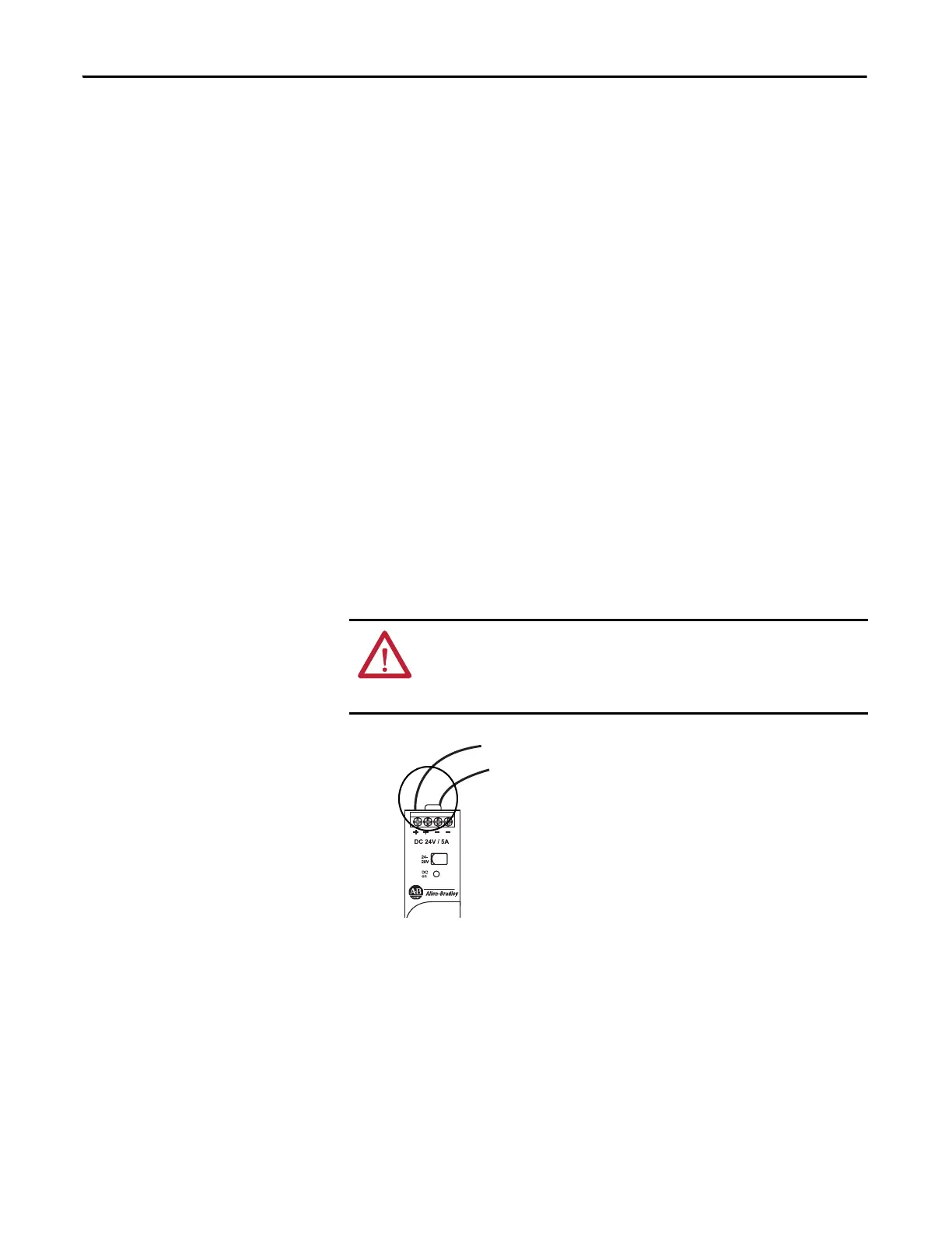
3. Connect wires to the 24V DC+ and 24V DC- connections on the external
24V DC power source.
WARNING: If you connect or disconnect wiring while the field-side power is on,
an electrical arc can occur. This could cause an explosion in hazardous location
installations. Be sure that power is removed or the area is nonhazardous before
proceeding.
 Loading...

