Configurable NAT Router 3
Rockwell Automation Publication 1783-PC017B-EN-P - May 2016
Linear and Star Network Considerations
When using the 1783-NATR router in a linear or star network, be sure that Ring Supervisor mode is not enabled.
By default, the 1783-NATR router is configured to be a non-supervisor ring node.
Device Level Ring (DLR) Network Considerations
When using the 1783-NATR router in a DLR network, consider whether the 1783-NATR router is a ring
supervisor. By default, the 1783-NATR router is configured to be a non-supervisor ring node. Use one of these
methods for controlling supervisor functionality:
• Use RSLinx Classic communication software or Studio 5000 Logix Designer programming software to set
the Ring Supervisor mode and other supervisor-related parameters. This method is the default method. If
you choose this option, follow the procedures that are outlined in the online help that accompanies the
software to enable Ring Supervisor mode.
• Use the DIP switches to automatically enable Ring Supervisor mode with the current supervisor-related
parameters stored in the memory of the 1783-NATR router. See Set the DIP Switches
on page 5 for
additional information.
Grounding Considerations
This product is intended to be mounted to a well-grounded mounting surface, such as a metal panel or DIN rail.
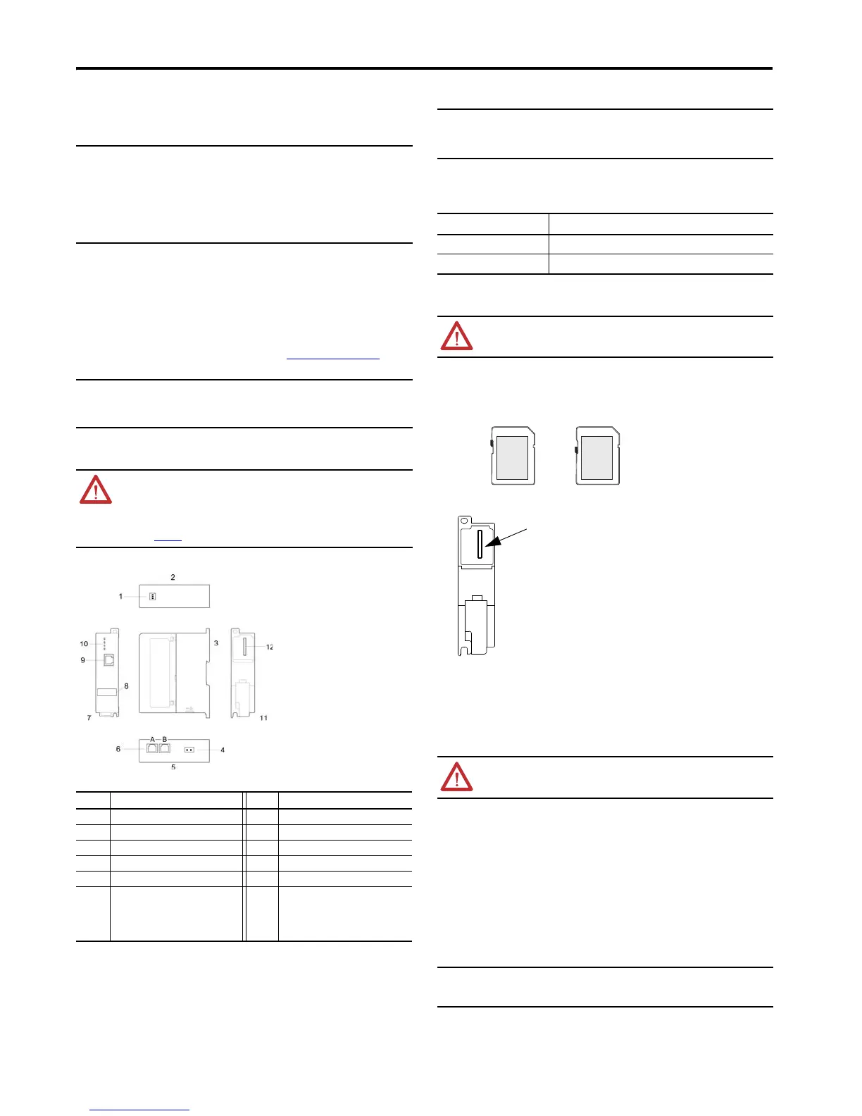
1783-NATR Router Components
By default, the individual ports on the 1783-NATR router auto-negotiate link speeds (10 Mbps or 100 Mbps) and
duplex setting (full or half).
Software Requirements
You must have these versions of software.
Install the SD Card
1. Remove the SD card from its original packaging, if necessary.
2. Verify that the SD card is locked or unlocked according to your preference. Consider the following when
deciding to lock the card before installation:
If the card is unlocked, the controller can write data to it or read data from it.
3. Locate the SD card slot on the rear of the 1783-NATR router.
4. Insert the SD card into the SD card slot.
You can install the SD card in only one orientation. The notch on the SD card points toward the top of the
device.
If you feel resistance when inserting the SD card, pull it out and change the orientation.
5. Gently press the card until it clicks into place.
Install the NAT Device
Follow these procedures to install the 1783-NATR router.
1. Mount the 1783-NATR router in one of these configurations:
• Panel mount
• DIN rail mount
2. Wire the 1783-NATR router.
3. Connect the Ethernet ports.
4. Download the EDS file for the 1783-NATR router.
5. Configure Internet Protocol settings.
6. Set the DIP switches.
This publication describes these steps in detail.
Mount the NAT Device
Install the 1783-NATR router on a DIN rail or panel mount the 1783-NATR router.
IMPORTANT DIP switch 3 is used to make the 1783-NATR router a ring supervisor in a DLR network. To
avoid adversely impacting communication in a linear or star network, take these
precautions:
• Make sure switch 3 remains in the Off position. If switch 3 is in the On position, the
1783-NATR router is automatically enabled as a ring supervisor.
• Make sure that the Ring Supervisor mode is not enabled in RSLinx® Classic
communication software or Studio 5000 Logix Designer™ programming software.
When switch 3 is in the Off position, the programming software controls whether the
1783-NATR router is a ring supervisor.
IMPORTANT Use these precautions when configuring a DLR network:
• Make sure that at least one node is acting as supervisor before connecting the last link
of a DLR network and physically closing the ring.
• Do not connect nodes that do not support a DLR as members of the ring.
ATTENTION: This product is grounded through the DIN rail to chassis ground. Use zinc plated
yellow-chromate steel DIN rail to assure proper grounding. The use of other DIN rail materials (for
example, aluminum or plastic) that can corrode, oxidize, or are poor conductors, can result in
improper or intermittent grounding. Secure DIN rail to mounting surface approximately every
200 mm (7.8 in.) and use end-anchors appropriately. Be sure to ground the DIN rail properly.
Refer to Industrial Automation Wiring and Grounding Guidelines, Rockwell Automation
publication 1770-4.1
, for more information.
Item Description Item Description
1DIP switches 7Front view
2Top view 8MAC ID label
3 Side view 9 Device port on front panel
4 DC connector 10 Status indicators
5Bottom view 11Rear view
6 Ports for connection to linear or ring
network
A: Port 1
B: Port 2
12 SD card slot
IMPORTANT Configure the Ethernet port on the device you connect to a 1783-NATR router so that it
matches the speed and duplex settings of the 1783-NATR router.
Failure to make the speed and duplex settings of directly connected devices match can
result in higher error rates, or loss of network connectivity.
Software Version
RSLinx Classic 3.70 or later
Studio 5000 Logix Designer 21 or later
WARNING: When you insert or remove the SD memory card while power is on, an electrical arc
can occur. This could cause an explosion in hazardous location installations.
Be sure that power is removed or the area is nonhazardous before proceeding.
WARNING: For hazardous location applications, use the supplied Weidmuller 1317570000
power terminal block.
IMPORTANT For 1783-NATR router:
When mounting the 1783-NATR router, allow a minimum clearance between product
and adjacent equipment of 2.54 cm (1 in.) on all sides.
 Loading...