7
For A-B Internal Use Only Publication 1785-6.2 March 1998
7. When the flash update is complete, cycle power to the processor.
8. Disconnect the serial cable that you used to perform the flash upgrade.
Step 4 - Applying the Firmware Revision Label
Important: It is important to apply this label to your processor to ensure you
receive the correct version back if you send it in for repair.
1. Turn off power to the processor.
2. Remove the processor from the chassis.
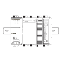
3. Apply the new firmware revision label in the space indicated by dotted lines
on the product identification label. The following figure shows where to
place the label on a series E PLC-5 processors and on older PLC-5 processors.
If the processor powers up with the: Do this:
PROC LED solid red and CH1A DH+ LED
blinking green (normally)
continue with the item 8, step 3 that
follows this table.
PROC LED flashing red/green
(flash mode)
Return to item 3, step 3 on page 5 and
repeat this section.
If you have repeated this item more
than 3 times, send the processor to
Allen-Bradley repair services.
PROC LED solid red and CH1A DH+
LED off
CAT. NO. REV.
1785-L40B E A01
PLC-5/40 PROCESSOR
MADE IN USA
PART NO. 96215074 A01
BACKPLANE CURRENT
REQUIREMENTS
3.3A AT 5VDC
Series E PLC-5 Processor Series C or Series D PLC-5 Processor
SERIES
D
F/W REV
B
FIRMWARE UPGRADE
CAT. NO.
1785-L40B
SERIES REV.
EB
41022
41023
Allen-Bradley Automation
 Loading...