Do you have a question about the Allen-Bradley 1769-L30ERM and is the answer not in the manual?
Resources containing information about related products from Rockwell Automation.
Considerations before installing a CompactLogix 5370 L1 controller.
Steps to reinstall or install an SD card into the controller.
Steps to install the CompactLogix 5370 L1 control system on a DIN rail.
Connect computer to the controller using a USB cable for firmware upgrades and program downloads.
Connect the controller to the EtherNet/IP network using an RJ45 Ethernet cable.
Considerations before installing a CompactLogix 5370 L2 controller.
Steps to reinstall or install an SD card into the controller.
Steps to install the CompactLogix 5370 L2 control system on a DIN rail or panel.
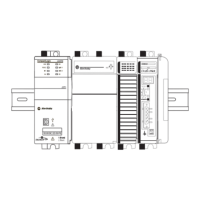
Considerations when planning your CompactLogix 5370 L3 control system.
Steps to reinstall or install an SD card into the controller.
Steps to install the CompactLogix 5370 L3 control system.
Set the IP address for a CompactLogix 5370 controller when commissioning.
Use BOOTP server to assign an IP address to your CompactLogix 5370 controller.
Use RSLinx software to set the IP address of the CompactLogix 5370 controller.
Use Logix Designer application to set the IP address of the controller via USB.
Use an SD card to set the IP address for a CompactLogix 5370 controller without software.
Change the IP address of a CompactLogix 5370 controller after system operation has begun.
Describes components a CompactLogix 5370 controller uses in a typical control system.
Describes functionality available with CompactLogix 5370 controllers.
Reduces possibility of using wrong device by comparing project device to installed device.
Explains EtherNet/IP network features, protocols, and capabilities for controllers.
Lists Ethernet node limits for CompactLogix controllers to account for I/O configuration.
Describes Device-level Ring, Linear, and Star network topologies supported by controllers.
Details I/O module options available for CompactLogix 5370 L1 control systems.
Explains how to connect field power to I/O devices using external power supplies.
Describes the embedded power supply and I/O module with digital input/output points.
Explains using 1734 POINT I/O modules as local expansion modules on the POINTBus backplane.
Details I/O module options available for CompactLogix 5370 L2 control systems.
Describes embedded I/O modules supported by CompactLogix 5370 L2 controllers.
Explains using Compact I/O modules as local expansion modules on a CompactBus backplane.
Steps to configure distributed I/O modules on an EtherNet/IP network.
Steps to configure distributed I/O modules on a DeviceNet network.
Details I/O module options available for CompactLogix 5370 L3 control systems.
Explains using Compact I/O modules as local expansion modules on a CompactBus backplane.
Includes distributed I/O modules over an EtherNet/IP network in the control system.
Includes distributed I/O modules over a DeviceNet network in the control system.
Validates the layout of I/O modules in the CompactLogix 5370 L3 control system.
Describes elements requiring planning for efficient application execution.
Explains using multiple tasks to schedule and prioritize program execution.
Describes programs for grouping data and logic and routines for executable code.
Defines a routine as a set of logic instructions providing executable code for a project.
Explains using tags (alphanumeric names) to address data (variables) in a controller.
Defines more information like limits and state identifiers for components within a controller project.
Details supported axes like AXIS_VIRTUAL and AXIS_CIP_DRIVE for controllers.
Specifies the maximum number of EtherNet/IP nodes and drives supported by controllers.
Explains Time Synchronization (CIP Sync) for accurate real-time synchronization of controllers and devices.
Steps to configure Integrated Motion by enabling time synchronization and adding a drive.
Describes options for loading projects back into controller user memory from an SD card.
Steps to store a project from the controller to the SD card.
Steps to use the application to load a project from an SD card.
Explains how to interpret status indicators and identify fault conditions in Logix Designer.
Displays recent fault information in Major Faults tab by checking connection tab options.
Shows controller status indicators for RUN, FORCE, I/O, OK, NS, LINK 1/2, and SD.
Compares CompactLogix L1 Series A and Series B controllers for power and firmware.
Notes no dimension differences between Series A and Series B controllers.
Illustrates Series B and Series A power supply wiring.
Provides examples for replacing controllers and updating firmware with requirements.
Explains connecting power to the Series A L1 controller via VDC+ and VDC- terminals.
Connects field power to I/O devices using external power supplies for Series A controllers.
Summarizes changes made in previous revisions of the manual.
| Input Voltage | 24V DC |
|---|---|
| Number of I/O | 30 |
| Ethernet Ports | 1 |
| Ethernet Port Speed | 10/100 Mbps |
| Power Supply | 24V DC |
| Series | CompactLogix |
| Controller Type | CompactLogix |
| Communication Ports | 1 Ethernet, 1 Serial |
| Serial Port Protocol | DF1, DH-485 |
| Operating Temperature | 0° to 60° C |
| Certifications | CE, UL, cUL |
| Product Type | Programmable Logic Controller (PLC) |