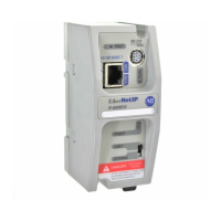
Addressing Reference
1785 PLC-5
7
This word of
the status file:
Stores:
S:1 Processor status and flags
Bit Description
0 RAM checksum is invalid at power-up
1 processor in RUN mode
2 processor in TEST mode
3 processor in PROG mode
4 processor burning EEPROM
5 enabled download operation
6 enabled test edit mode
7 mode select switch in REMOTE position
8 forces enabled
9 forces present
10 processor successfully burned EEPROM
11 preforming online programming
12 not defined
13 user program checksum done
14 last scan of ladder or SFC step
15 processor
started first program scan or the first scan of the
next step in
an SFC
S:2 Switch Setting information
• bits 0 – 7 DH+ station number
• bits 11–12 are set based on the I/O chassis backplane switches
bit 12
bit 11 = I/O chassis addressing
0 0 illegal
1 0 1/2 -slot
0 1 1-slot
1 1 2-slot
• bit 13: 1 = load from EEPROM
• bit 14: 1 = RAM backup not configured
• bit 15: 1 = memory unprotected
S:3 to S:6 Active Node table for channel 1A
Word
Bits DH+ Station #
3 0-15 00-17
4 0-15 20-37
5 0-15 40-57
6 0-15 60-77
S:7 Global status bits:
• low 8 bits – rack fault bits for racks 0-7
• high 8 bits – rack queue-full bits for racks 0-7
S:8 Last program scan (in ms)
S:9 Maximum program scan (in ms)
 Loading...